Multi-position height adjustment system for a pipe handling apparatus

a technology of multi-position height adjustment and pipe handling, which is applied in the direction of mechanical equipment, drilling pipes, pipe laying and repair, etc., can solve the problems of increasing the travel of hydraulic actuators, increasing the cost of double-tape, and not readily adapting the upper end to a range of different rig floor heights

Active Publication Date: 2007-01-16
FORUM US
View PDF10 Cites 47 Cited by
  • Summary
  • Abstract
  • Description
  • Claims
  • Application Information

AI Technical Summary

Benefits of technology

[0007]In a preferred aspect of the invention a pipe handling apparatus has a base fit with a boom capable of positioning a proximal end at a plurality of elevations adjacent a rig floor. The proximal end of the boom is raised and lowered using a pivoting arm connected between the base and the boom. The distal end of the boom is spaced away from the rig flow and moves slidably along the base. The boom is hinged at the pivoting arm at one or tow or more hinge points preferably comprising a hinge pin and two or more boom ports corresponding with two or arm ports for forming corresponding sets of boom and arm ports. The hinge pin can be engaged with one of the two of more sets of boom and arm ports. Hence a multi-position height adjustment of the boom can be achieved without overextending the pivoting arm. Further, and more preferably, the boom ports are arranged at a predetermined spacing so that each boom port, when lowered to the base, aligns with each corresponding arm ports arranged at the same predetermined spacing such that the hinge pin can be alternatively engaged with any with one of the two of more aligned sets of boom and arm ports. Geometrically, this results in consistent positioning of the distal end of the boom when lowered.

Problems solved by technology

Although effective to raise the upper end to a predetermined height H, this type of prior art pipe handling apparatus does not readily permit adaptation to raise the upper end to a range of different rig floor heights.
This in turn increases hydraulic actuator travel, requiring a more expensive type of double-acting hydraulic ram, also capable of pulling a load upon it's return and under a more onerous mechanical disadvantage.
The increase in hydraulic travel also requires more time and may not allow the apparatus to keep pace with the pipe handling crew thereby resulting in decreased productivity.
The over-extension of the arm also raises additional wear-and-tear, maintenance, safety and structural concerns.

Method used


Image

  • Multi-position height adjustment system for a pipe handling apparatus
  • Multi-position height adjustment system for a pipe handling apparatus
  • Multi-position height adjustment system for a pipe handling apparatus

Examples


Embodiment Construction

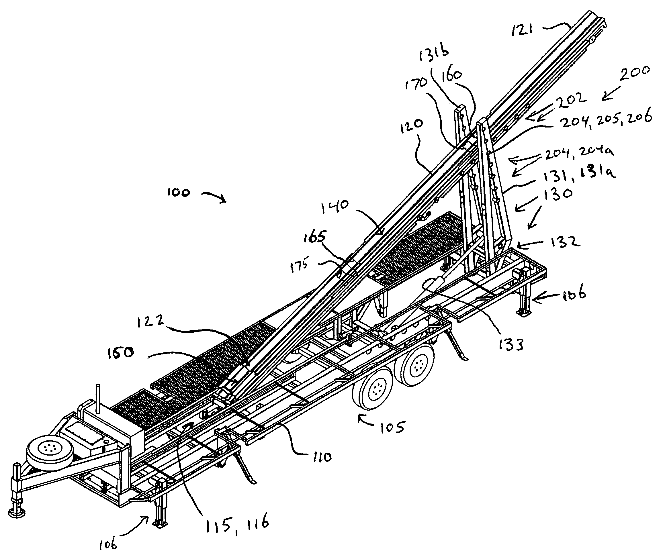
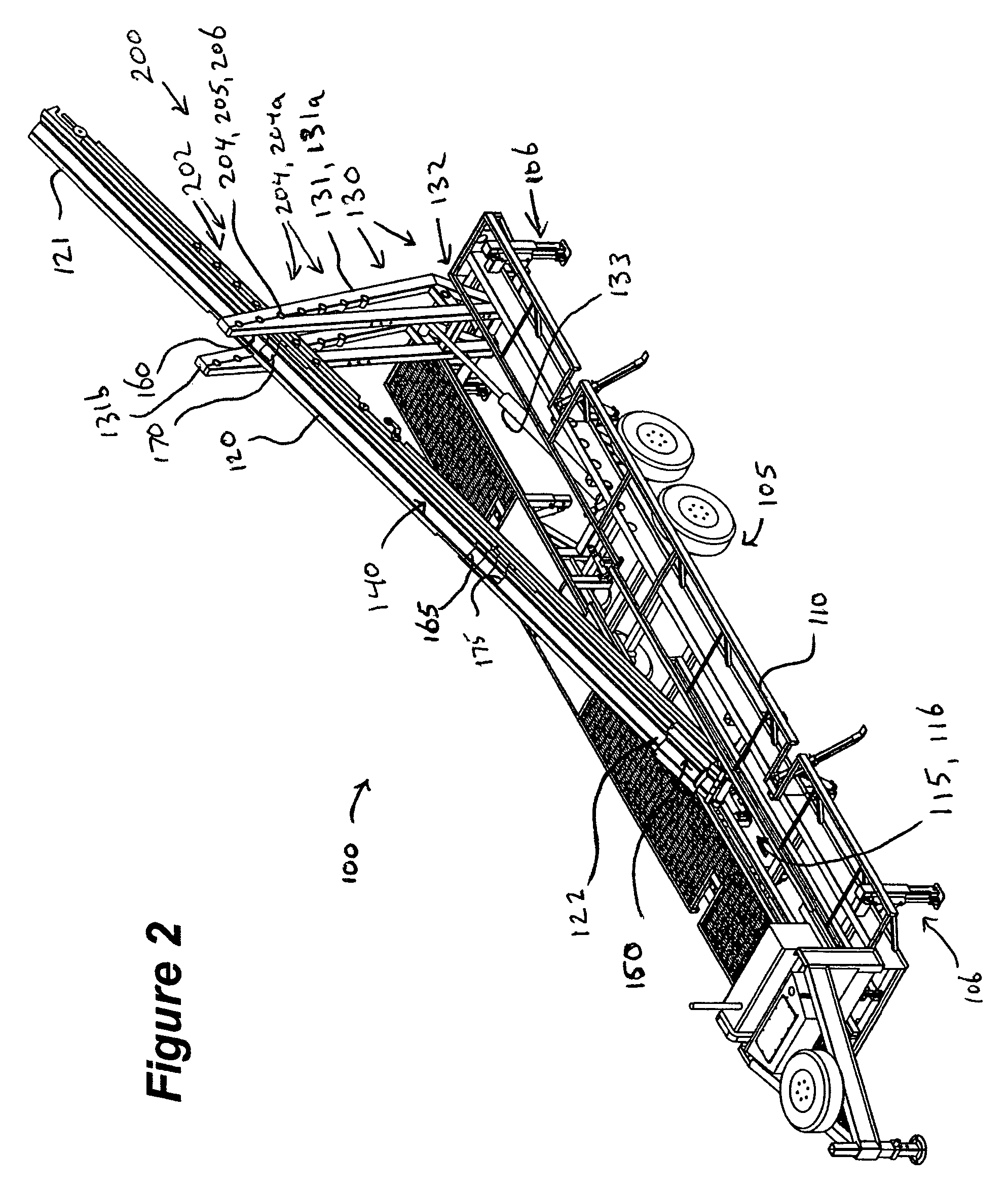
[0028]Referring to FIG. 2 and generally of FIGS. 2–10c, an embodiment of a pipe handling apparatus 100 is shown comprising a multi-position height adjustment system 200. The pipe handling apparatus 100 comprises a longitudinal base 110 mounted on an undercarriage assembly 105. Boom 120 is shown with a proximal end 121 in a raised position and positioned towards a derrick work floor (not shown) and a distal end 122 adjacent the base 105. Herein, the terms proximal and distal are used in relation to the a rig floor, the extreme end of the boom adjacent the floor being referred to as the proximal end 121.

[0029]Actuating means 130 are operable to raise the boom 120 and lower the boom substantially parallel to the base 110. The boom is preferably nestled in a cavity 115. As the boom 120 is raised out of the cavity, the proximal end 121 moves towards the derrick work floor with the distal end 122 moving along longitudinal cavity 115. The movement of distal end 122 is guided by track means...


PUM


Abstract

A system for adjusting the height of a boom on a pipe handling apparatus. A cavity is formed in the base between proximal and distal ends. The boom is nestable in said cavity and has a distal end guided along the base. A pivoting member is pivotally coupled to said boom for raising a proximal end for positioned adjacent a work floor for handling of pipe therebetween. A plurality of ports are arranged along the boom at a pre-determined spacing. A plurality of ports are is similarly arranged along the same predetermined spacing along the pivoting member. The spacing of the boom and arm ports is such that a hinge pin can engage any one of corresponding pairs of boom and arm port when the boom is lowered to nestle inside the cavity as each boom port corresponds with an arm port.

Description

FIELD OF THE INVENTION[0001]The present invention relates generally to pipe handling systems and in particular to a system for providing drill pipe to, and receiving drill pipe from, work floors of a derrick or rig which may be positioned at various heights from the ground.BACKGROUND OF THE INVENTION[0002]Drill strings of pipe for oil and gas wells are assembled or disassembled vertically on a derrick one joint at a time, and are stored horizontally on pipe racks situated on the ground adjacent the rig. The work floor of the rig is typically elevated substantially above the pipe rack such that transferring sections of pipe to and from the work floor and the racks is necessary and requires careful handling of the heavy pipe to protect the workers and the pipe.[0003]As shown in FIG. 1, a common prior art solution in the context of a transportable trailer is a pipe handling apparatus implementing a base supporting a pivoting boom having a pipe receiving trough along its upper surface. ...

Claims


Application Information

Patent Timeline
Patent Type & Authority Patents(United States)
IPC IPC(8): B66F11/00E21B19/15
CPCE21B19/155
Inventor HANDLEY, RICHARD A.
Owner FORUM US
Why Eureka
Try Eureka