Walking leg support

a leg support and walking technology, applied in the field of walking leg support, can solve the problems of not being able to be correctly reattached, easily removed, and affording little protection to the foot of the apparatus, so as to reduce shock and load, dissipate force, and be easy to remove and replace.

Inactive Publication Date: 2007-01-16
R G PARTNERSHIP
View PDF33 Cites 24 Cited by
  • Summary
  • Abstract
  • Description
  • Claims
  • Application Information

AI Technical Summary

Benefits of technology

[0005]It is accordingly an object of the invention to provide apparatus with a portion that attaches to a cast, brace, or orthotic on the leg at or below the knee. It is another object that the apparatus provide a boot portion for protecting the foot and securing the base of the cast or orthosis. It is another object that the apparatus provide a subfloor portion spaced below the boot portion, toward which the boot portion is gradually forced when body weight is applied to the leg during walking to reduce shock and load to the lower leg, foot, and ankle. It is yet another object that the apparatus provide means for adjusting the degree of spring resistance to movement of the boot portion toward the subfloor by easy replacement of certain spring members. It is yet another object that the apparatus provide means for easily removing and replacing the majority of the apparatus when not walking without the need for adjustment. It is yet another object that the apparatus provide means for wholly or partially unloading the patient's weight and ground reaction forces by transfer of the load to the upper calf and tibia. It is yet another object that resilient members dampen and help dissipate these forces. It is yet another object to provide spring propulsion of the leg through the gait cycle for enhanced ambulation.

Problems solved by technology

The apparatus affords little protection for the foot, and is not easily removed when not walking, or correctly reattached when needed.

Method used


Image

  • Walking leg support
  • Walking leg support
  • Walking leg support

Examples


Embodiment Construction

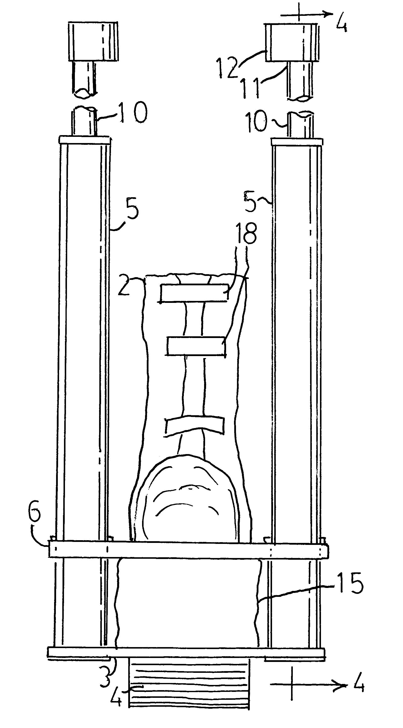
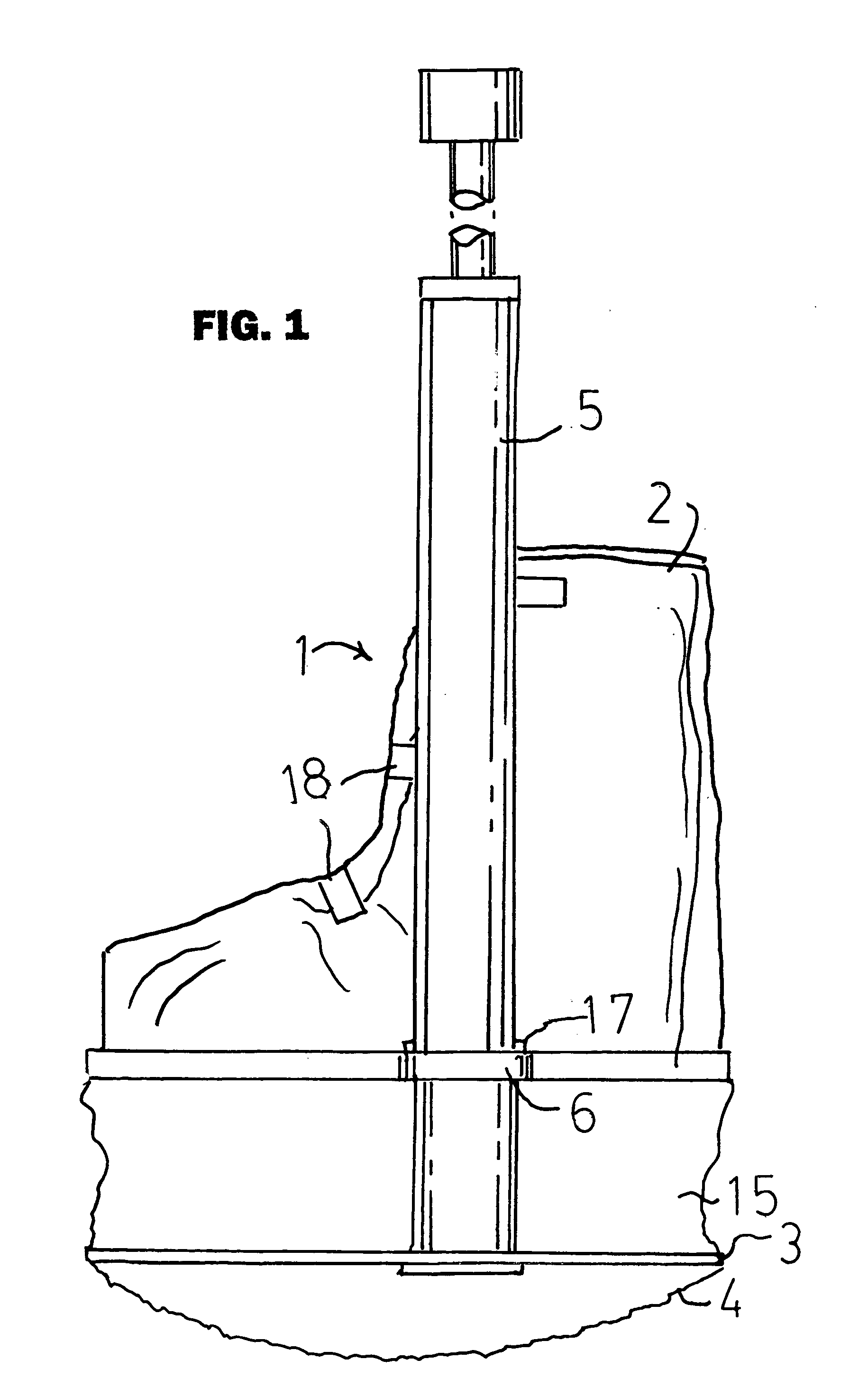
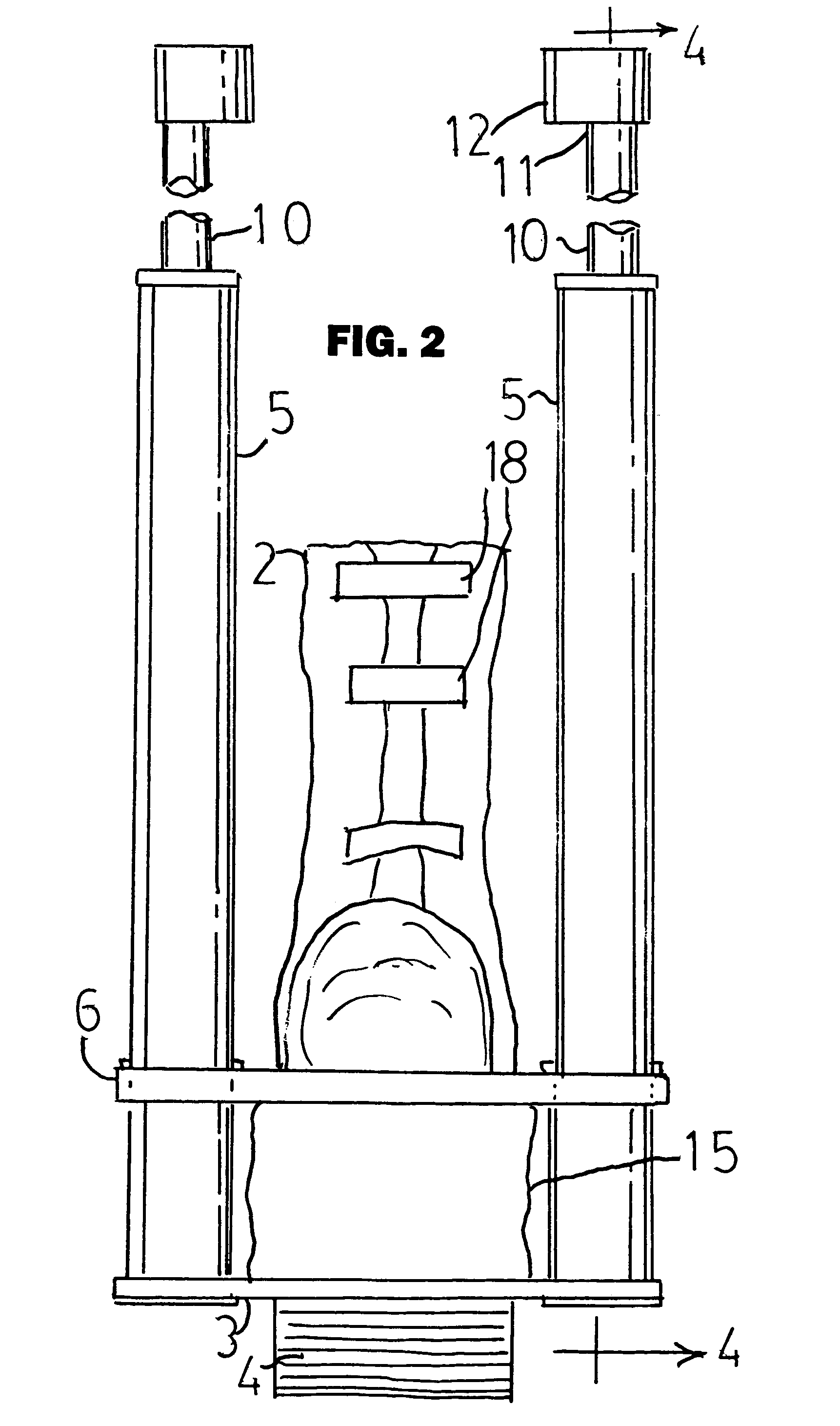
[0011]Referring now to the drawing Figures, the walking support 1 of the invention has a boot portion 2 for removably receiving the foot of a person who is in need of some means of reducing the shock received to the foot in walking. This may include people suffering from diabetic foot ulcers, fractures of the bones of the lower leg, foot, or ankle, for example. The boot portion 2 may be supplied with fasteners well known in the art, such as the hook and loop fasteners 18 shown. The leg may be in a cast, orthosis, brace, or the like. A subfloor portion 3 positioned below the boot portion has a resilient arcuate or rocker bottom surface 4 that hits the pavement first when walking. A pair of elongate tubular members 5 are affixed to the subfloor portion 3 and extend upward therefrom. The boot portion is slidably mounted by mounting means 6 so as to be freely movable up and down on the tubular members 5. A pair of elongate elements 10 have a first end 11 provided with means 12 for mount...


PUM


Abstract

Apparatus attaches to the leg at or below the knee to take the shock of walking off the foot and ankle. The foot is encased in a boot. Two spaced-apart tubes extend upward from a subfloor mounted below the boot. The boot is mounted for sliding up and down on the tubes. A pair of parallel elongate rods are attached at their upper ends to the upper portion of the leg at or below the knee, such that the lower ends of the rods are in the tubes. A spring, preferably a gas compression spring, is inserted into each tube so that the lower end of each rod compresses the spring as body weight is put on the subfloor in walking. The subfloor moves toward the boot as the springs are compressed, reducing some of the shock of walking and transferring forces to the leg. The rods may be attached to the leg by a cast, brace or orthosis.

Description

[0001]Applicants claim priority of provisional patent application Ser. No. 60 / 512,402, filed Oct. 20, 2003.[0002]This invention relates to leg supports and more particularly to supports applied to the lower leg to facilitate walking for patients with leg and foot disabilities.BACKGROUND OF THE INVENTION[0003]Various devices are known such as casts, braces, cuffs, and splints that are designed to protect and stabilize the lower leg, ankle and foot when walking as they heal from injury or disorders such as diabetic ulcers.[0004]U.S. Pat. No. 2,206,234 issued Jul. 2, 1940 to Murray discloses an invalid walking and apparatus that attaches to a cast or the leg below the knee that has a support plate for the foot. A cushioned member is suspended below the foot support. When body weight is put on the leg during walking, the cushioned member is forced up toward the foot support. Springs interposed between the cushioned member and the rest of the apparatus are compressed by the body weight. ...

Claims


Application Information

Patent Timeline
Patent Type & Authority Patents(United States)
IPC IPC(8): A61F5/00A43B7/24A63B25/08E04G1/00
CPCA43B7/00A61F5/0195A43B13/18
Inventor ROCHE, MARTINGRAHAM, MARK
Owner R G PARTNERSHIP
Why Eureka
Try Eureka