
Method for driving plasma display panel

a plasma display and display panel technology, applied in the direction of instruments, static indicating devices, etc., can solve the problem of impossible display of a right gradation, and achieve the effect of stable discharg

Inactive Publication Date: 2007-01-16
LG ELECTRONICS INC
View PDF2 Cites 10 Cited by
  • Summary
  • Abstract
  • Description
  • Claims
  • Application Information

AI Technical Summary

Benefits of technology

[0037]An object of the present invention is to provide a method for driving a plasma display panel, in which a more stable discharge is possible even at a high temperature.

Problems solved by technology

However, referring to FIG. 4, if the related art PDP is operated at a high temperature, the low second DC voltage Zdc2 and data pulse voltage form excessive wall charges between the scan electrode Y and the sustain electrode Z, which causes erratic discharge between the scan electrode Y and the sustain electrode Z in the address period, making display of a right gradation impossible.

Method used


Image

  • Method for driving plasma display panel
  • Method for driving plasma display panel
  • Method for driving plasma display panel

Examples


Embodiment Construction

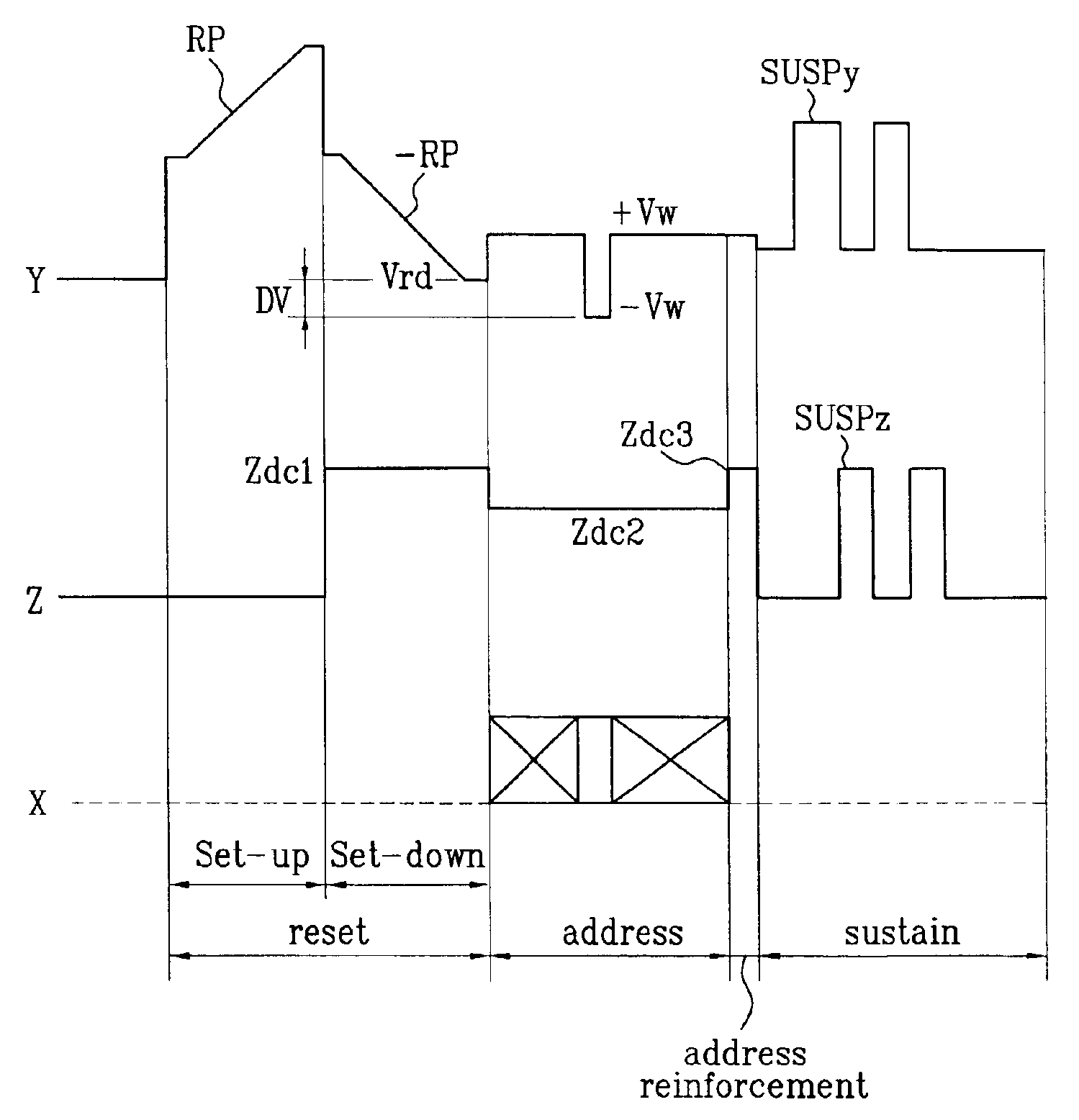
[0055]Reference will now be made in detail to the preferred embodiments of the present invention, examples of which are illustrated in the accompanying drawings FIGS. 5 and 6A-6D. FIG. 5 illustrates a waveform diagram showing operative waveforms in driving a PDP in accordance with a preferred embodiment of the present invention.

[0056]Referring to FIG. 5, each sub-field of a PDP is divided into a reset period for resetting an entire screen, an address period for selecting cells, an address reinforcement period for reinforcing wall charges at the cells before the sustain period, and a sustain period for sustaining discharges at the selected cells.

[0057]The reset period is divided into a set up time period and a set down time period. In the set up time period, a reset pulse of ramp-up waveform is provided to the scan electrode, and, in the set up time period, a reset pulse of ramp-down waveform is provided to the scan electrode

[0058]In the reset period, a reset pulse of ramp-up wavefor...


PUM


Abstract

Method for driving a plasma display panel, wherein an address reinforcement period is added between an address period and a sustain period, and a scan voltage Vw of positive polarity and a third DC voltage Zdc3 are applied, for inducing floating charges in discharge cells, whereby preventing erratic discharge caused by the floating charges at a high temperature.

Description

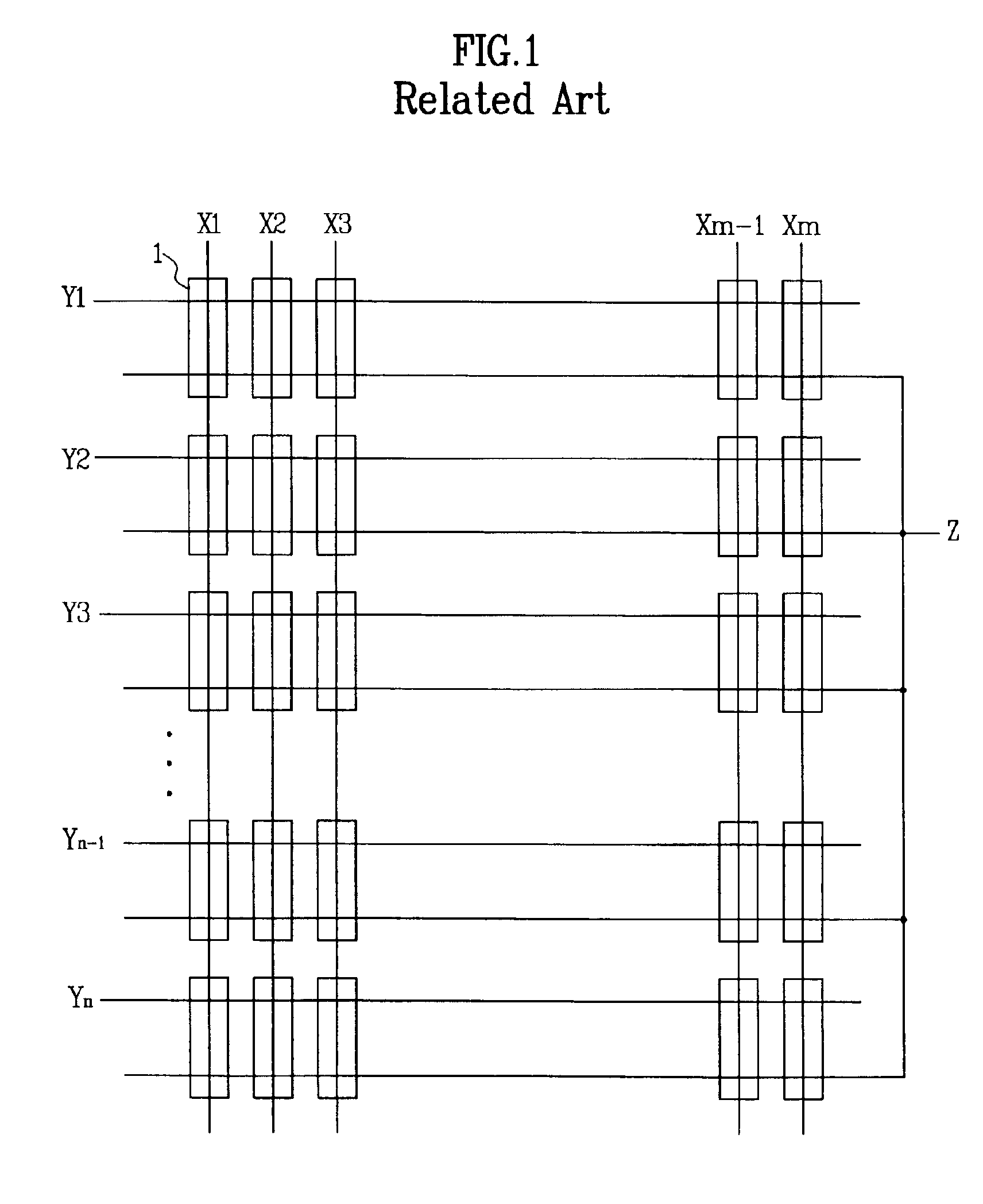
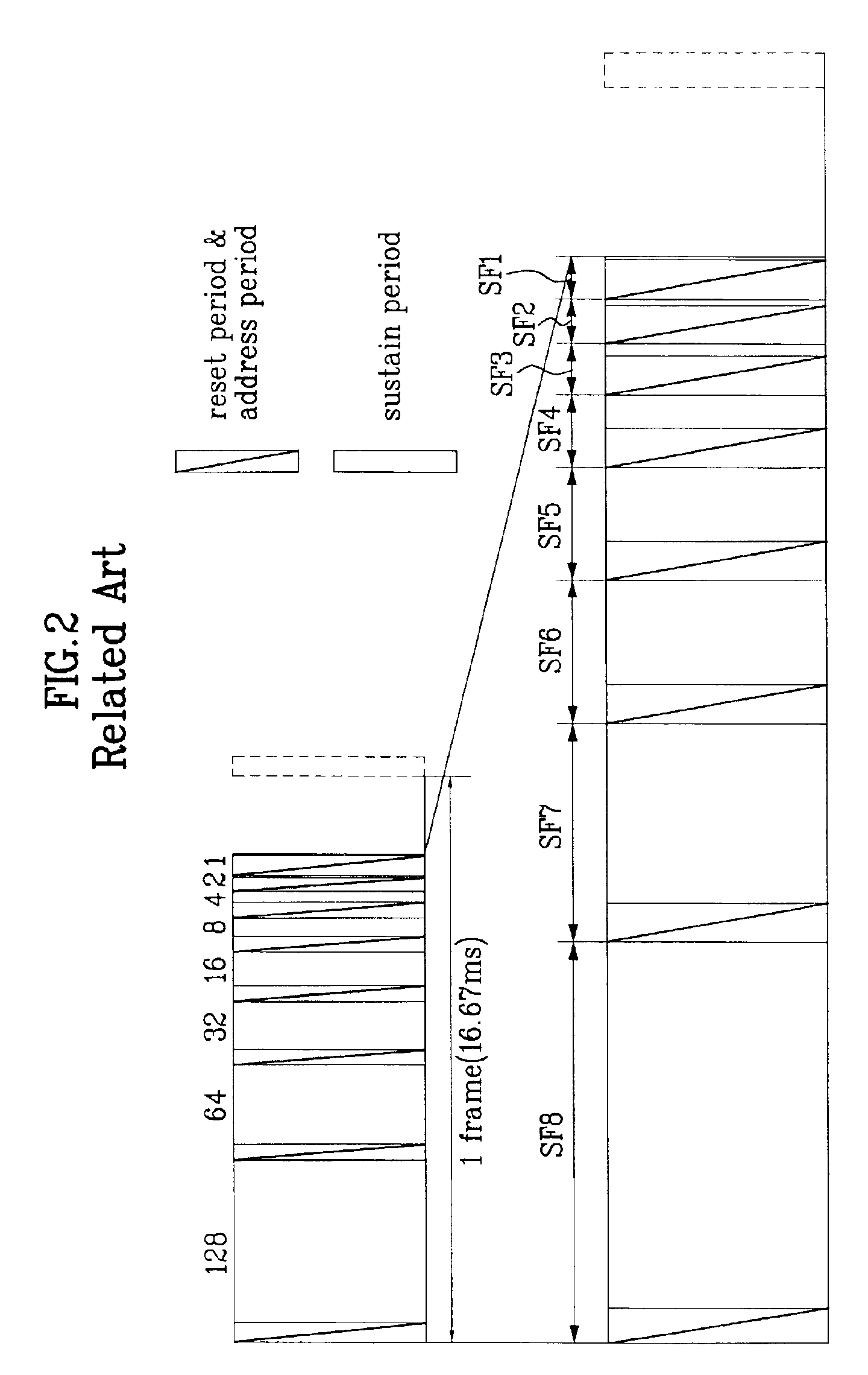
[0001]This application claims the benefit of the Korean Application No. P2002-18546 filed on Apr. 4, 2002, which is hereby incorporated by reference.BACKGROUND OF THE INVENTION[0002]1. Field of the Invention[0003]The present invention relates to a plasma display panel, and more particularly, to a method for driving a plasma display panel, which can prevent erratic discharge of the plasma display panel caused by high temperature.[0004]2. Background of the Related Art[0005]The plasma display panel (hereafter called as “PDP”) is a device for displaying a picture including characters, or graphics by making phosphor luminescent by a UV ray emitted when inert gas mixture (He+Xe, Ne+Xe, or He+Xe+Ne) discharges. The PDP has advantages in that fabrication of a large sized thin PDP is easy, and provides a picture quality improved significantly owing to recent technical development.[0006]Typically, the PDP is provided with three electrodes driven by an AC voltage, which is called as an AC surf...

Claims


Application Information

Patent Timeline
Patent Type & Authority Patents(United States)
IPC IPC(8): G09G3/28G09G3/20G09G3/288G09G3/291G09G3/292G09G3/293G09G3/294G09G3/298
CPCG09G3/2022G09G3/293G09G2310/066G09G3/296
Inventor MYOUNG, DAE JINKIM, DAI HYUNKIM, GEUN SOO
Owner LG ELECTRONICS INC
Learn More