Variable speed fan drive

a variable speed, fan technology, applied in the direction of engine cooling apparatus, belt/chain/gearing, engine cooling apparatus, etc., can solve the problems of inefficiency, durability, power consumption, etc., and achieve the effect of reducing power consumption, reducing reliability, and eliminating excess heat generation and its deteriorating effects

Inactive Publication Date: 2007-01-23
DEERE & CO
View PDF17 Cites 23 Cited by
  • Summary
  • Abstract
  • Description
  • Claims
  • Application Information

AI Technical Summary

Benefits of technology

[0006]A further object of the invention is to provide a variable speed fan drive where power requirements are matched to the cooling system more precisely, resulting in lower power consumption and thus less fuel use.
[0009]Other objects of the invention are attained by a variable speed fan drive for a vehicle, the vehicle powered by an internal combustion engine, the fan drive comprising: a drive side assembly having a variable sheave assembly, the variable sheave assembly being rotationally driven by a shaft, the shaft being driven by the engine of the vehicle, the variable sheave assembly being variably actuated by a hydraulic actuator assembly; a driven side assembly having a sheave assembly mounted to a shaft, the shaft being drivingly connected to a fan; a v-belt engaging both the sheave assembly of the drive side assembly and the sheave assembly of the driven side assembly so that a variable ratio is attained between the drive side variable sheave assembly and the driven side sheave assembly when the hydraulic actuator assembly is actuated, so that the speed of the fan is varied.
[0011]Still other objects of the invention are attained by a method of varying the speed of a fan of a vehicle powered by an internal combustion engine, comprising the steps of: driving a variable sheave assembly using the internal combustion engine; driving a second sheave assembly connected to a fan via a belt from the variable sheave assembly; and, selectively providing pressurized engine oil from an oil galley of the internal combustion engine to a hydraulic actuator via an electronically controlled hydraulic valve based upon vehicle or engine operating parameters, thereby selectively actuating the variable sheave assembly using the hydraulic actuator so as to vary the ratio between the variable sheave assembly and the second sheave assembly, thereby varying the speed of the fan.

Problems solved by technology

The viscous fan drive is intended to modulate fan speed and thus air flow, with the resulting power consumption to meet the cooling needs of the vehicle in an optimal manner in an effort to conserve power and fuel.
Current drives are cost effective, yet are sized to achieve the lowest cost thereby resulting in durability issues.
Additionally, the fans are not as efficient as desired, especially at the mid-point of the modulation range where the desired fan speed for effective cooling resides for a very high percentage of the time in typical work vehicle applications.
The problem is that at mid-range fan speeds the combination of moderate speed and moderate torque combine to produce large heat loads that both consume power and generate heat thereby deteriorating the fan drive and thus its reliability.

Method used


Image

  • Variable speed fan drive
  • Variable speed fan drive
  • Variable speed fan drive

Examples


Embodiment Construction

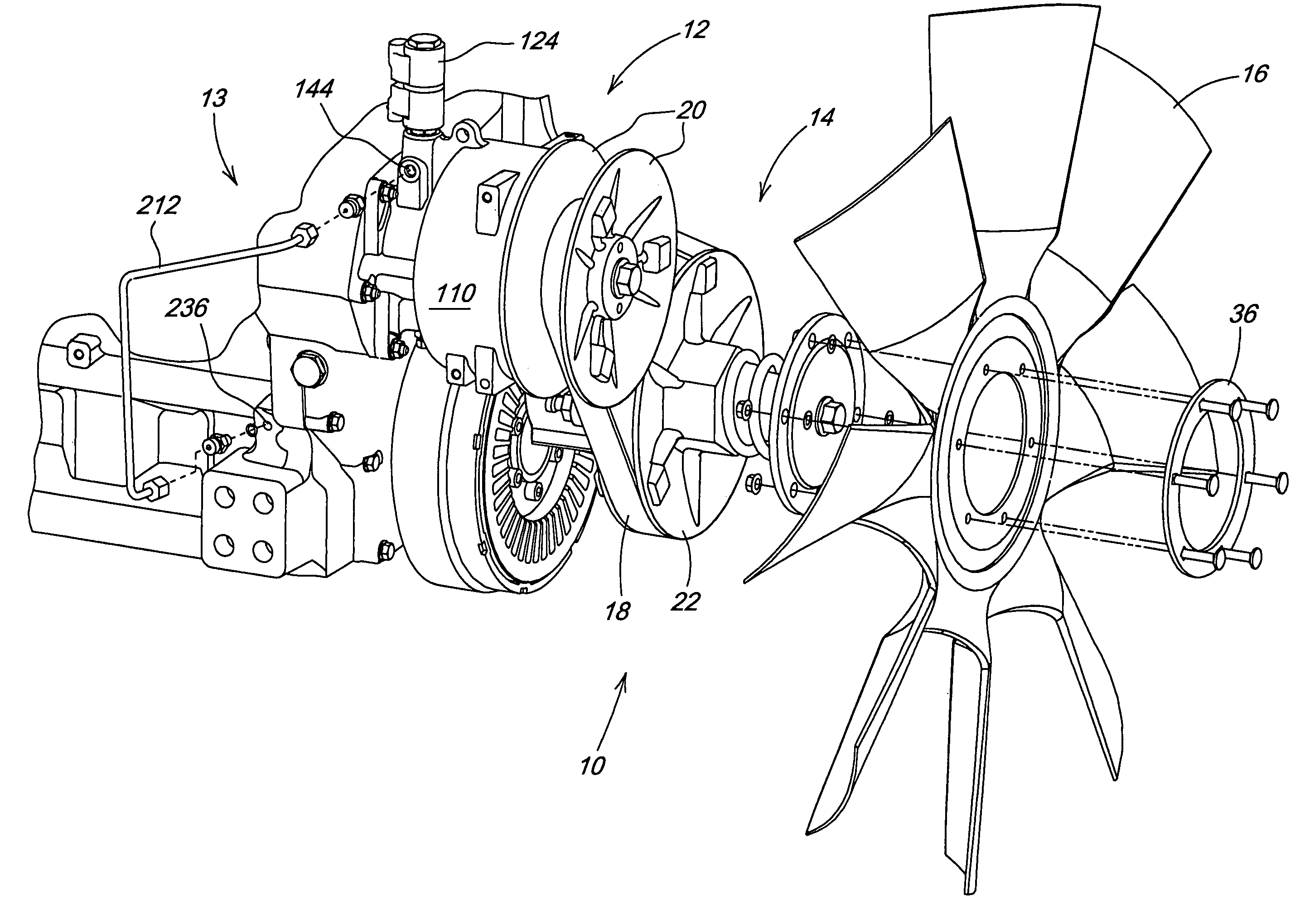
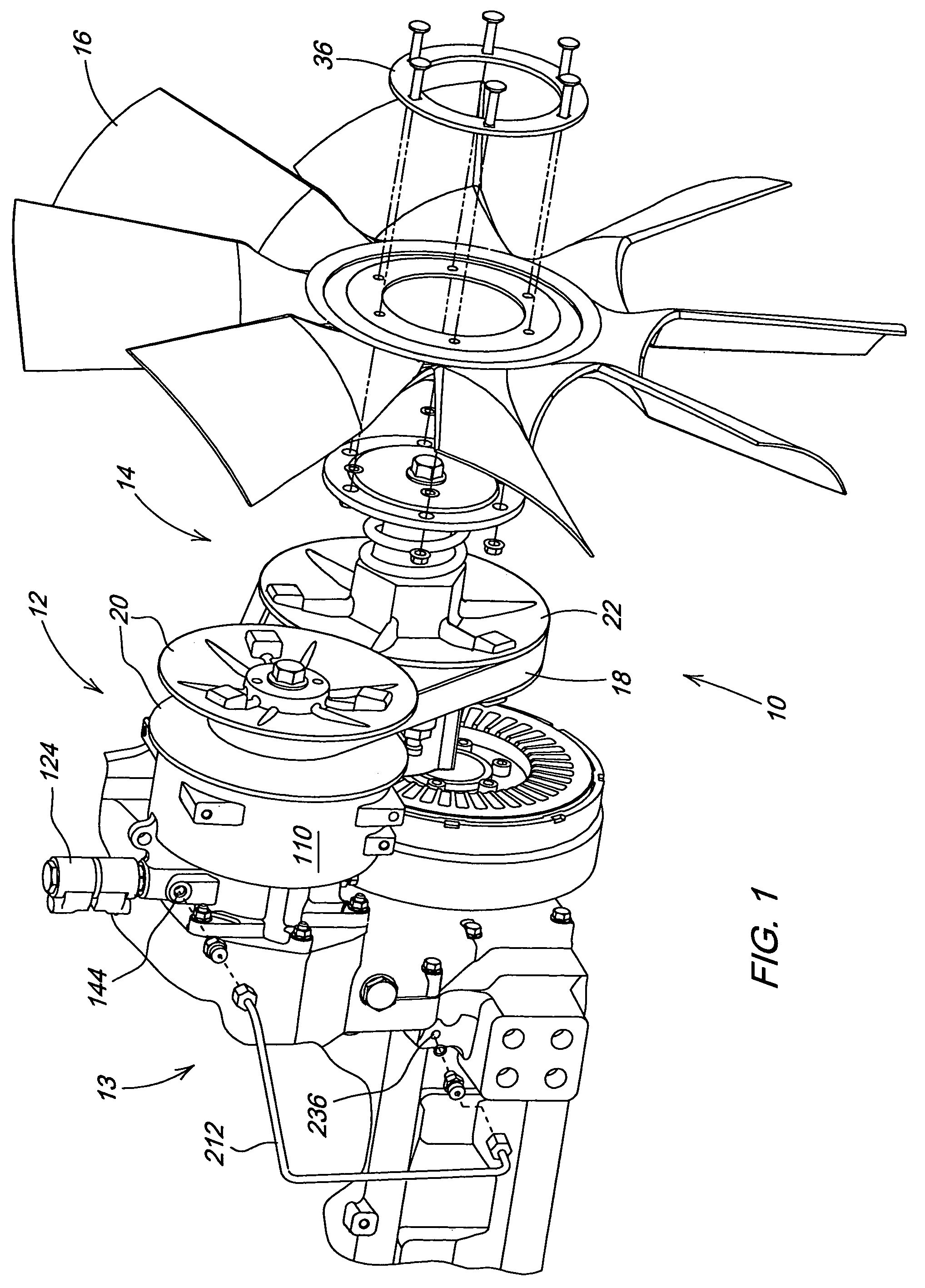
[0024]With reference now to the drawings and particularly FIG. 1, it can be seen that a variable speed fan drive is designated generally by the numeral 10. As shown the fan drive 10 is comprised generally of a drive side assembly 12 which is operatively connected with an engine 13 of a vehicle, and a driven side assembly 14 which is operatively connected with a cooling fan 16. Power is transmitted from the drive side assembly 12 to the driven side assembly 14 by way of a v-belt 18 that engages a sheave assembly 20 on the drive side assembly 12, and a sheave assembly 22 on the driven side assembly 14.

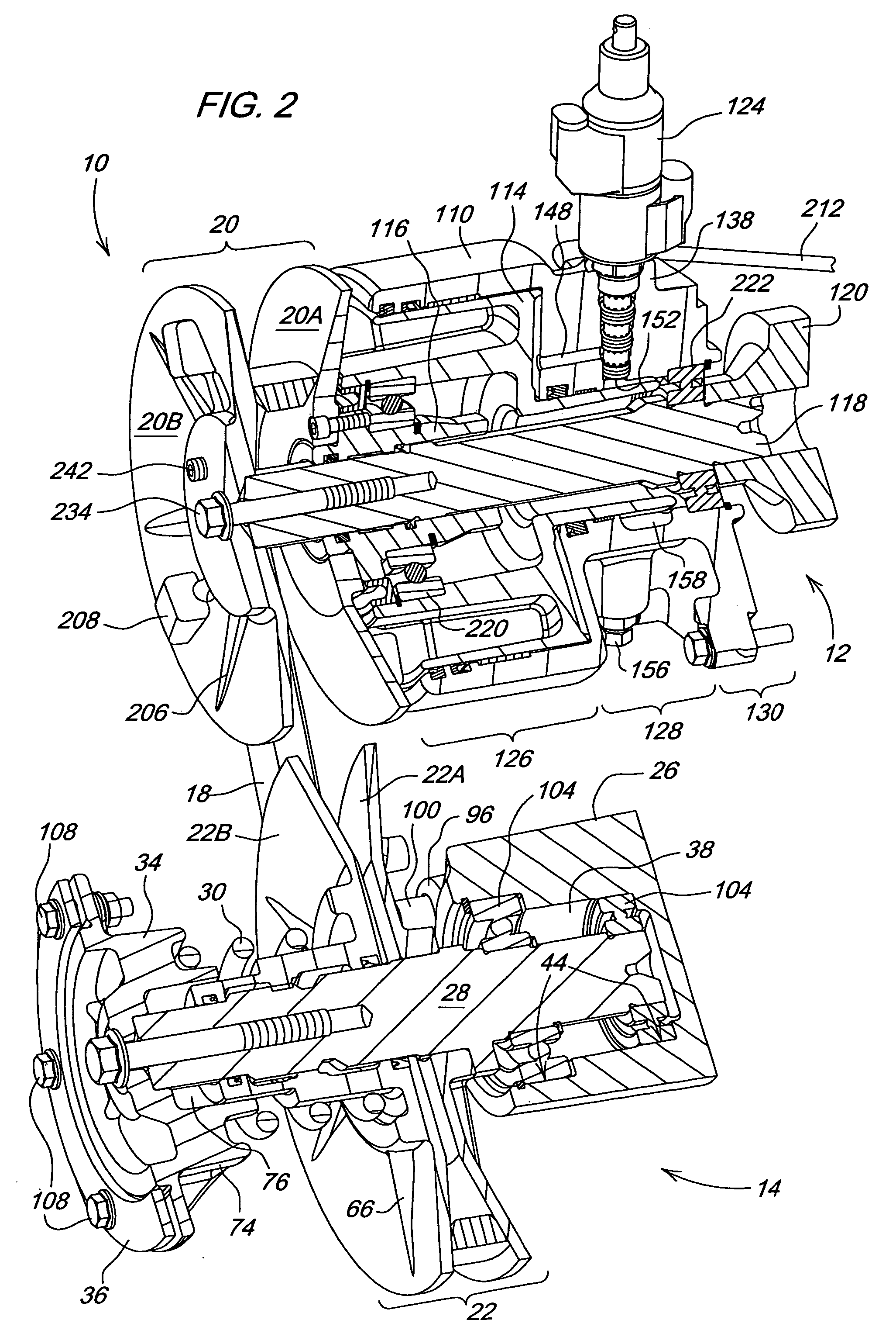
[0025]Referring now to FIGS. 2, 3 and 5 it can be seen that the driven side assembly 14 generally comprises a housing 26, a shaft 28, first and second sheave halves 22A and 22B, a compression spring 30, a fan hub 34, and a fan support ring 36. The driven side housing 26, as illustrated, is in the form of a water pump housing having a cylindrical shaft and bearing support portion 38. Thos...


PUM


Abstract

A variable fan drive for a vehicle powered by an internal combustion engine is provided. A drive side assembly utilizes a hydraulic actuator to actuate a variable sheave assembly. The variable sheave assembly drives a sheave assembly of a driven side assembly by way of a v-belt. The hydraulic actuator has a piston coupled to the variable sheave assembly. The piston is hydraulically translated by pressurized engine oil from the internal combustion engine. An electronically controlled solenoid valve controlled by an engine or vehicle controller selectively controls the flow of engine oil for piston actuation. Thus the speed of the fan can be controlled based on various engine or vehicle operating parameters.

Description

FIELD OF THE INVENTION[0001]The present invention relates generally to cooling fans for vehicles. More particularly, the present invention relates to drive mechanisms for such fans. Specifically, the present invention relates to variable speed fan drives that can be controlled based on various vehicle parameters.BACKGROUND OF THE INVENTION[0002]Current variable speed fan drive systems used in work vehicles such as agricultural tractors typically use a viscous drive on the system cooling fan. The viscous fan drive is intended to modulate fan speed and thus air flow, with the resulting power consumption to meet the cooling needs of the vehicle in an optimal manner in an effort to conserve power and fuel. Current drives are cost effective, yet are sized to achieve the lowest cost thereby resulting in durability issues. Additionally, the fans are not as efficient as desired, especially at the mid-point of the modulation range where the desired fan speed for effective cooling resides for...

Claims


Application Information

Patent Timeline
Patent Type & Authority Patents(United States)
IPC IPC(8): F01P7/02
CPCF16H9/18F01P7/046
Inventor BOWMAN, DENNIS AARONKEEN, ERIC ALBERTAPPLETON, ANDY BLAINE
Owner DEERE & CO
Why Eureka
Try Eureka