Vertically-aligned (VA) liquid crystal display device

a liquid crystal display and vertical alignment technology, applied in the field of vertical alignment of liquid crystal display devices, to achieve the effect of raising contras

Inactive Publication Date: 2007-01-23
SHARP KK
View PDF75 Cites 123 Cited by
  • Summary
  • Abstract
  • Description
  • Claims
  • Application Information

AI Technical Summary

Benefits of technology

[0015]An object of the present invention is to improve a viewing angle characteristic of a VA liquid crystal display, and to realize a VA liquid crystal display exhibiting a viewing angle characteristic that is as good as the one exhibited by the IPS mode or better than it while permitting the same contrast and operation speed as the conventional liquid crystal displays.

Problems solved by technology

As described above, there are some problems to realize a division of orientation directions of the liquid crystalline molecules for improving the viewing angle performance in the VA LCD.

Method used


Image

  • Vertically-aligned (VA) liquid crystal display device
  • Vertically-aligned (VA) liquid crystal display device
  • Vertically-aligned (VA) liquid crystal display device

Examples


first embodiment

[0316]FIGS. 18A and 18B are diagrams showing the position of a liquid-crystal injection port of the liquid crystal panel 100 of the first embodiment through which a liquid crystal is injected. As described later, in the process of assembling components to produce a liquid-crystal panel, after the CF substrate and TFT substrate are bonded to each other, a liquid crystal is injected. As far as a VA type TFT LCD is concerned, it takes much time to inject a liquid crystal compared with the TN LCD in general. Since protrusions are formed, it takes much more time to inject a liquid crystal. For shortening the time required for injecting the liquid crystal, as shown in FIG. 18A, a liquid-crystal injection port 102 should preferably be formed on a side vertical to the direction in which the protrusions are arrayed parallel to one another on a cyclic basis. Reference numeral 101 denotes a sealing line.

[0317]During injection of a liquid crystal, when the interior of the panel is deaerated thr...

second embodiment

[0319]After an intermediate voltage is applied to the panel of the second embodiment, the interior of the panel is observed using a microscope. The observation has revealed that very stable alignment is attained.

[0320]Furthermore, in the panel of the first embodiment, a response speed has quite improved. FIGS. 20A to 21 are diagrams indicating a changing value of the response speed permitted by the panel of the first embodiment in relation to changes in parameters that are an applied voltage and a spacing (gap) between upper and lower protrusions. FIG. 20A indicates an on speed (for transition from 0 to 5 V), FIG. 20B indicates an off speed (for transition from 5 to 0 V), and FIG. 21 indicates a switching speed that is a sum of the on speed and off speed. As shown in FIGS. 20A to 21, a fall time off is hardly dependent on the spacing but a rise time on varies greatly. The smaller the spacing is, the higher the response speed becomes. Incidentally, the thickness of cells is 3.5 micro...

fourth embodiment

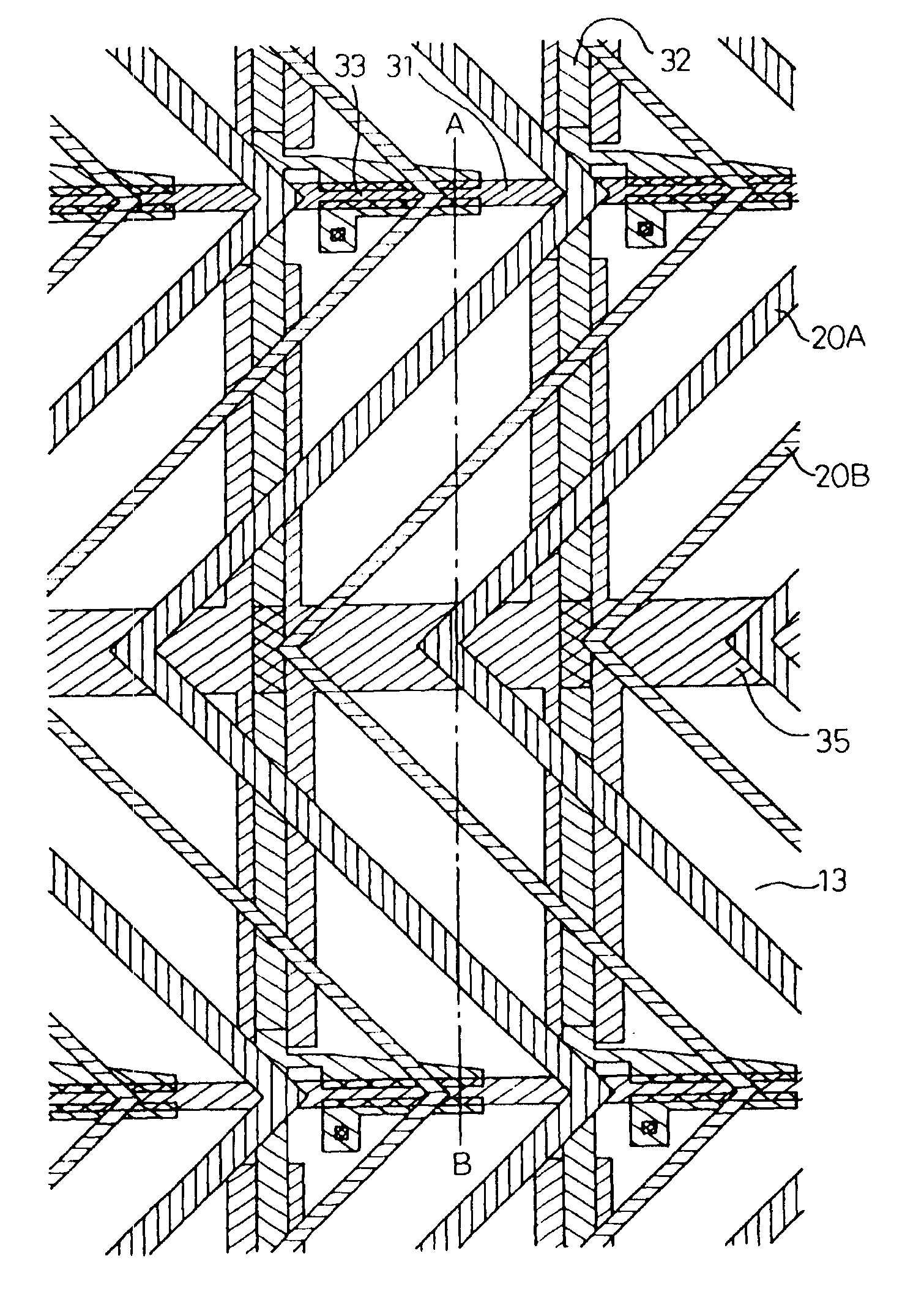
[0335]Moreover, in a modification of the fourth embodiment, as shown in FIG. 37B, tapered juts 46 are formed on each protrusion 20. Even in this case, the length of each tapered portion is about 50 micrometers or less than it. For creating a pattern of this kind of protrusions, the pattern is drawn using a positive resist, and the protrusions 20 are created by performing slight etching. A positive resist whose thickness is about a half of the height of the protrusions is applied, and the tapered juts 46 on the protrusions 2 are left intact by performing slight etching. With the juts, the alignment of liquid crystalline molecules near the apices of the juts can be controlled.

[0336]FIGS. 38A and 38B are diagrams showing the structure of a panel in the fifth embodiment. FIG. 38A is a diagram illustratively showing a state in which the panel is seen obliquely, and FIG. 38B is a side view. The fifth embodiment is an example in which the structure of a panel corresponds to the structure s...


PUM

PropertyMeasurementUnit
viewing angleaaaaaaaaaa
polar angleaaaaaaaaaa

Abstract

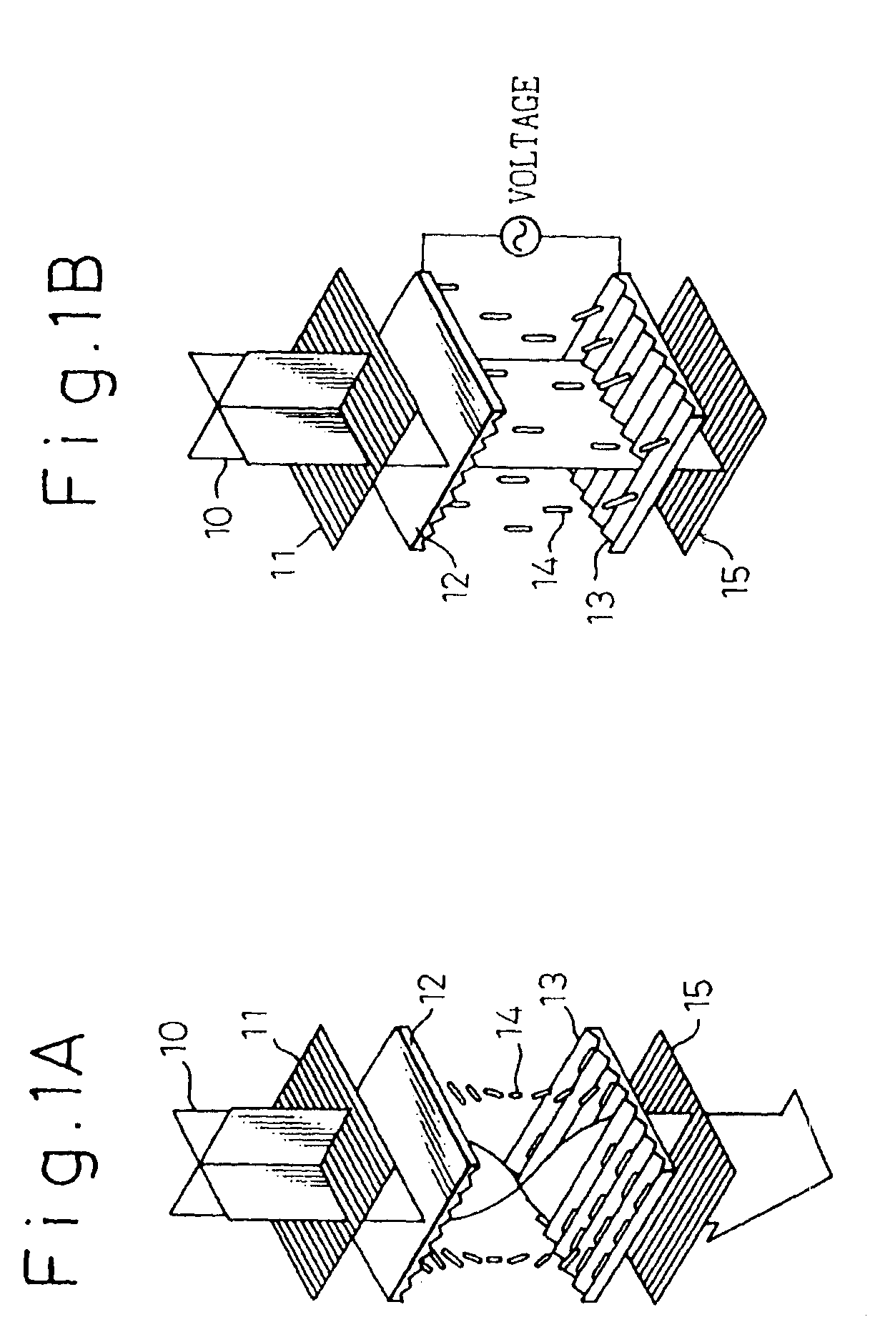
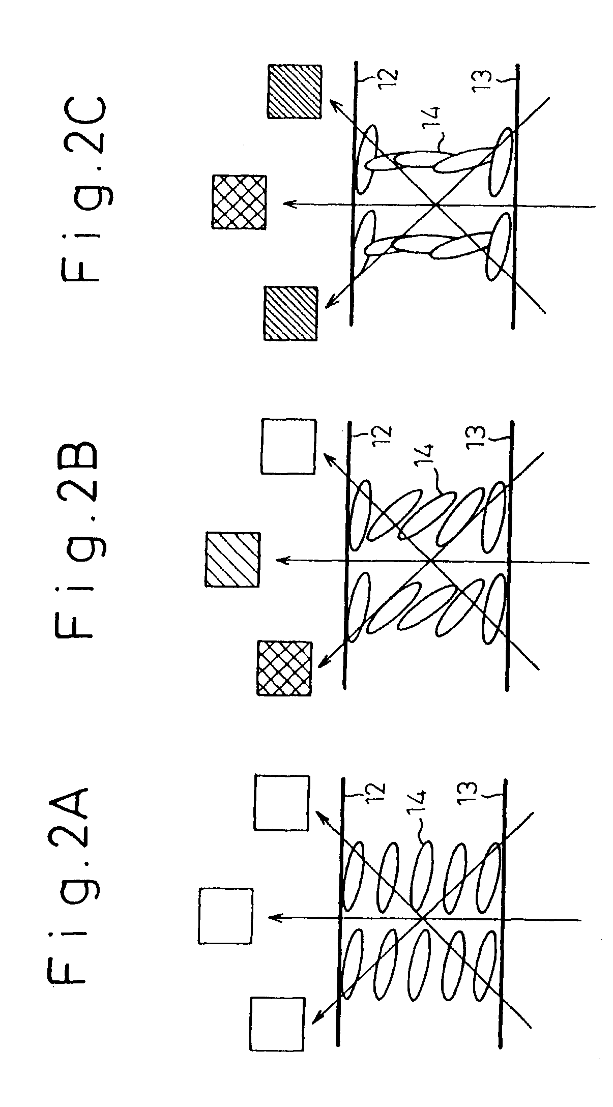
A vertically alignment mode liquid crystal display device having an improved viewing angle characteristic is disclosed. The disclosed liquid crystal display device uses a liquid crystal having a negative anisotropic dielectric constant, and orientations of the liquid crystal are vertical to substrates when no voltage being applied, almost horizontal when a predetermined voltage is applied, and oblique when an intermediate voltage is applied. At least one of the substrates includes a structure as domain regulating means, and inclined surfaces of the structure operate as a trigger to regulate azimuths of the oblique orientations of the liquid crystal when the intermediate voltage is applied.

Description

[0001]This is a divisional of application Ser. No. 09 / 097,027, filed Jun. 12, 1998, now U.S. Pat. No. 6,724,452.BACKGROUND OF THE INVENTION[0002]The present invention relates to a liquid crystal display (LCD), or more particularly, to a technology for realizing orientation division for a vertically-aligned (VA) LCD.[0003]Among flat-panel displays enjoying image quality equivalent of the one offered by the CRT, it is a liquid crystal display (LCD) that has been most widely adopted nowadays. In particular, a thin-film transistor (TFT) type LCD (TFT LCD) has been adapted to public welfare-related equipment such as a personal computer, word processor, and OA equipment, and home electric appliances including a portable television set, and expected to further expand its market. Accordingly, there is a demand for further improvement of image quality. A description will be made by taking the TFT LCD for instance. However, the present invention is not limited to the TFT LCD but can apply to ...

Claims


Application Information

Patent Timeline
Patent Type & Authority Patents(United States)
IPC IPC(8): G02F1/1343G02F1/1333G02F1/1335G02B5/20G02B5/30G02F1/13363G02F1/1337G02F1/1339G02F1/136G02F1/1368G02F1/137G02F1/139G09F9/30G09F9/35
CPCG02F1/133707G02F1/133753G02F1/134336G02F1/1393G02F1/133512G02F1/133514G02F2413/10G02F2001/133388G02F1/134309G02F1/133388G02F1/1337
Inventor TAKEDA, ARIHIROOHMURO, KATSUFUMIKOIKE, YOSHIOKATAOKA, SHINGOSASAKI, TAKAHIROSASABAYASHI, TAKASHITSUDA, HIDEAKICHIDA, HIDEOOHASHI, MAKOTOOKAMOTO, KENJIYAMAGUCHI, HISASHIOTANI, MINORUMORISHIGE, MAKOTOFURUKAWA, NORIAKIKAMADA, TSUYOSHITANAKA, YOSHINORIHOSHINO, ATUYUKIHAYASHI, SHOUGOTAKIZAWA, HIDEAKIKINJOU, TAKESHITACHIBANAKI, MAKOTOIMOTO, KEIJIHASEGAWA, TADASHIYOSHIDA, HIDEFUMIINOUE, HIROYASUTANIGUCHI, YOJIFUJIKAWA, TETSUYAMURATA, SATOSHISAWASAKI, MANABUTANOSE, TOMONORIHIROTA, SIROIKEDA, MASAHIROTASHIRO, KUNIHIROTSUKAO, KOUJITASAKA, YASUTOSHIMAYAMA, TAKATOSHITANUMA, SEIJINAKANISHI, YOHEI
Owner SHARP KK
Why Eureka
Try Eureka