
Optoelectronic transceiver with power voltage supply detection

Active Publication Date: 2007-01-23
LUMENTUM JAPAN INC
View PDF11 Cites 9 Cited by
  • Summary
  • Abstract
  • Description
  • Claims
  • Application Information

AI Technical Summary

Benefits of technology

[0010]In this way, the optical transmission equipment with more than one power supply can, when turning on the power supplies, set predetermined operating condition of the functional circuits in the equipment in response to the timing of the last turn-on of the power supply, thus providing stable operation of the equipment.

Problems solved by technology

However, the optical transmission equipment may use a segmented power supply, in cases such as analog and digital mixed circuits used in the equipment, to keep noise generated in one circuit from interfering with other circuits.
This may cause an unstable operation or a malfunction of the optical transmission equipment, such as inadequate reading of the desired set information, depending on when each power supply is turned on.

Method used


Image

  • Optoelectronic transceiver with power voltage supply detection
  • Optoelectronic transceiver with power voltage supply detection
  • Optoelectronic transceiver with power voltage supply detection

Examples


Embodiment Construction

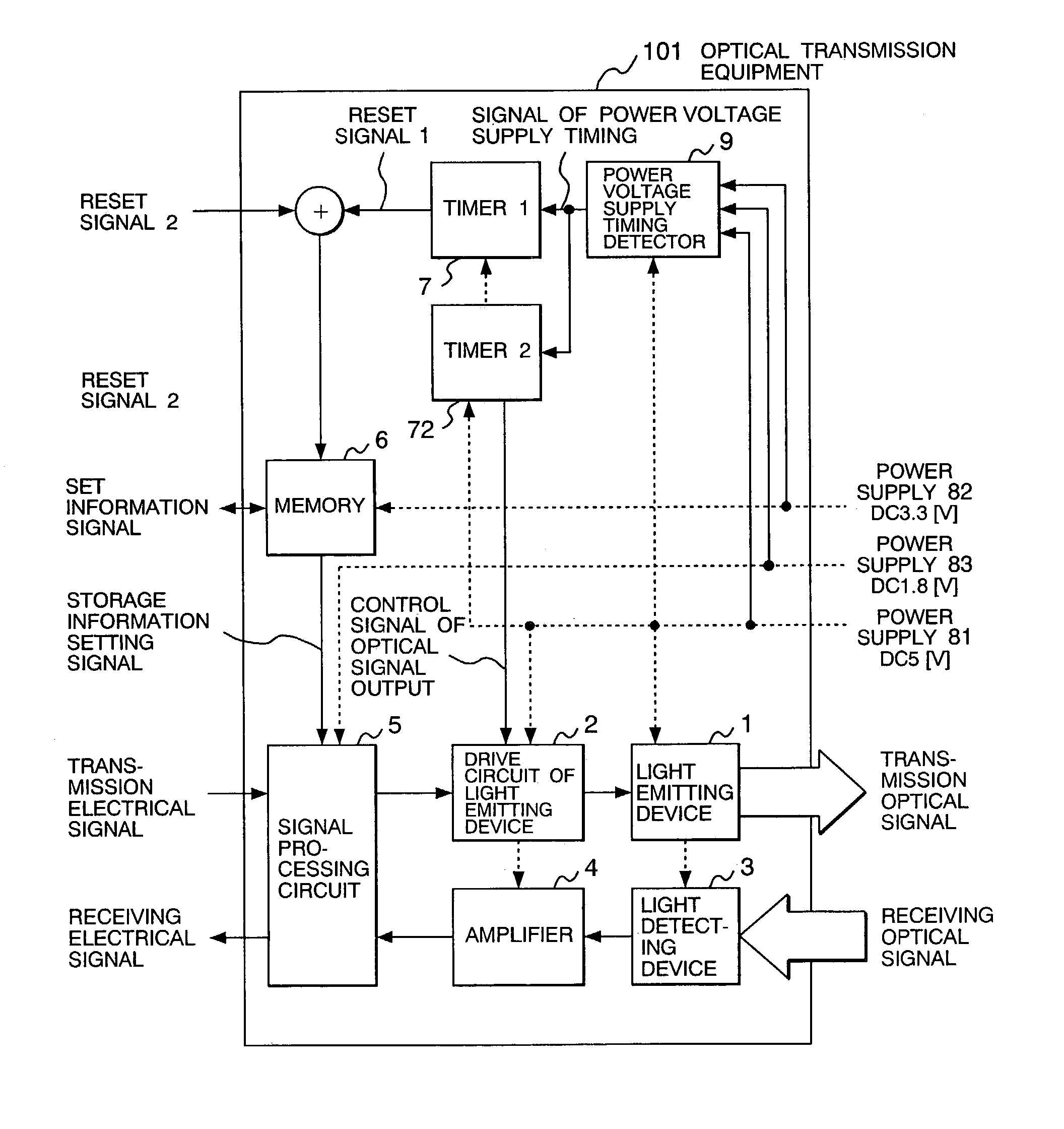
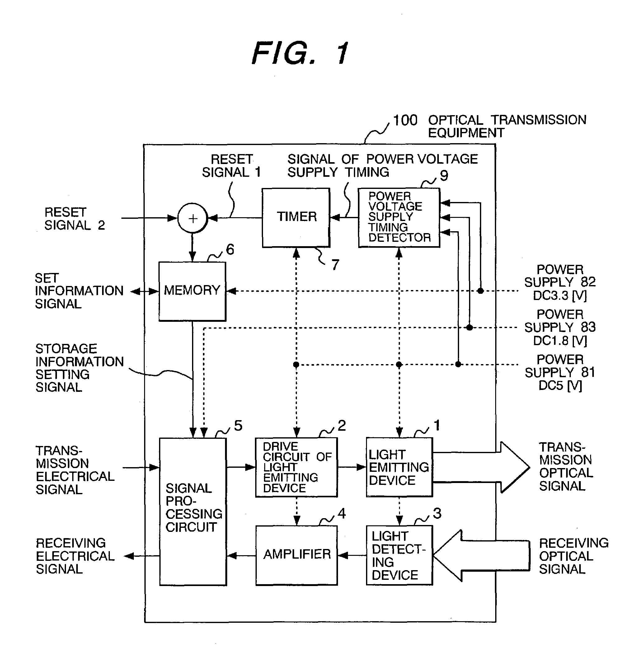
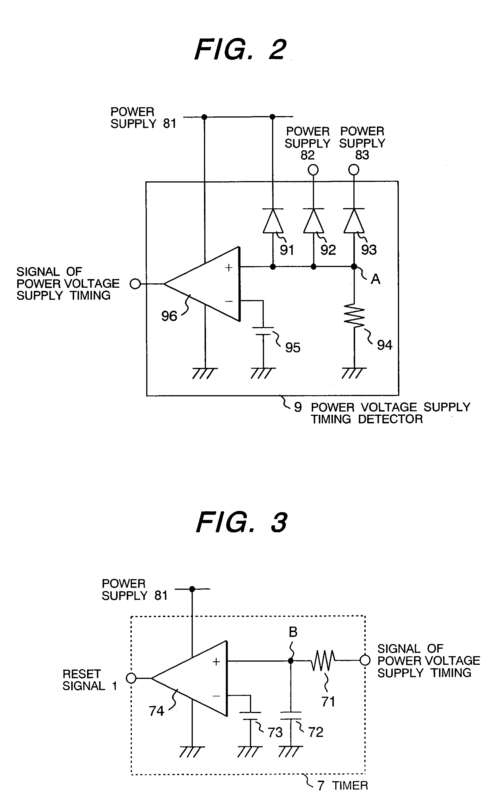
[0018]FIG. 1 shows a function block diagram of optical transmission equipment 100 according to the first embodiment of the present invention. The optical transmission equipment 100 includes a light emitting device 1, drive circuit 2 of the light emitting device, light detecting device 3, amplifier 4, signal processing circuit 5, memory 6, and timer 7. The signal processing circuit 5 can perform processings such as code modulation or computing of the transmission electrical signal and the output signal of the amplifier 4. Information stored in the memory 6 can set the function of the signal processing circuit 5. In other words, the memory 6 is a means for setting predetermined operating condition of the signal processing circuit 5. External set information signal can provide the set information on the code modulation and computing processings. The memory 6 can store the provided set information. The memory 6 can send the storage information setting signal to the signal processing cir...


PUM


Abstract

Optical transmission equipment with more than one power supply which can, when turning on the power supplies, set predetermined function of a signal processing circuit after a predetermined time period after the last turn-on of the power supply and can enable the operation of a drive circuit of the light emitting device after an additional predetermined time period.

Description

BACKGROUND OF THE INVENTION[0001]The present invention relates to optical transmission equipment, and more particularly, to the improvement of the optical transmission equipment which uses more than one power supply for the circuit elements in the equipment.[0002]Conventional optical transmission equipment prevents malfunction when turning on the power supply, in a manner such as that described in Japanese application patent laid-open publication No. Hei 07-210272. This application discloses to provide a forced discharge circuit in a reset circuit when turning on the power supply to prevent false output of the received output even in the case of power supply voltage return after very short voltage drop.[0003]However, the optical transmission equipment may use a segmented power supply, in cases such as analog and digital mixed circuits used in the equipment, to keep noise generated in one circuit from interfering with other circuits. The optical transmission equipment with more than ...

Claims


Application Information

Patent Timeline
IPC IPC(8): H04B10/00H04B10/80
CPCH04B10/00
Inventor TOKITA, SHIGERUTANAKA, TOMOKAZUANTONY, CLEITUSTONODUKA, TAROUNOGUCHI, MASAZUMI
Owner LUMENTUM JAPAN INC
Learn More