Method and structure for implementing a layered object windows

a technology of object windows and layers, applied in the field of computer software, can solve the problems of inability to easily understand, high cost of solutions, and small information size,

Inactive Publication Date: 2007-01-23
MICROSOFT TECH LICENSING LLC
View PDF5 Cites 113 Cited by
  • Summary
  • Abstract
  • Description
  • Claims
  • Application Information

AI Technical Summary

Benefits of technology

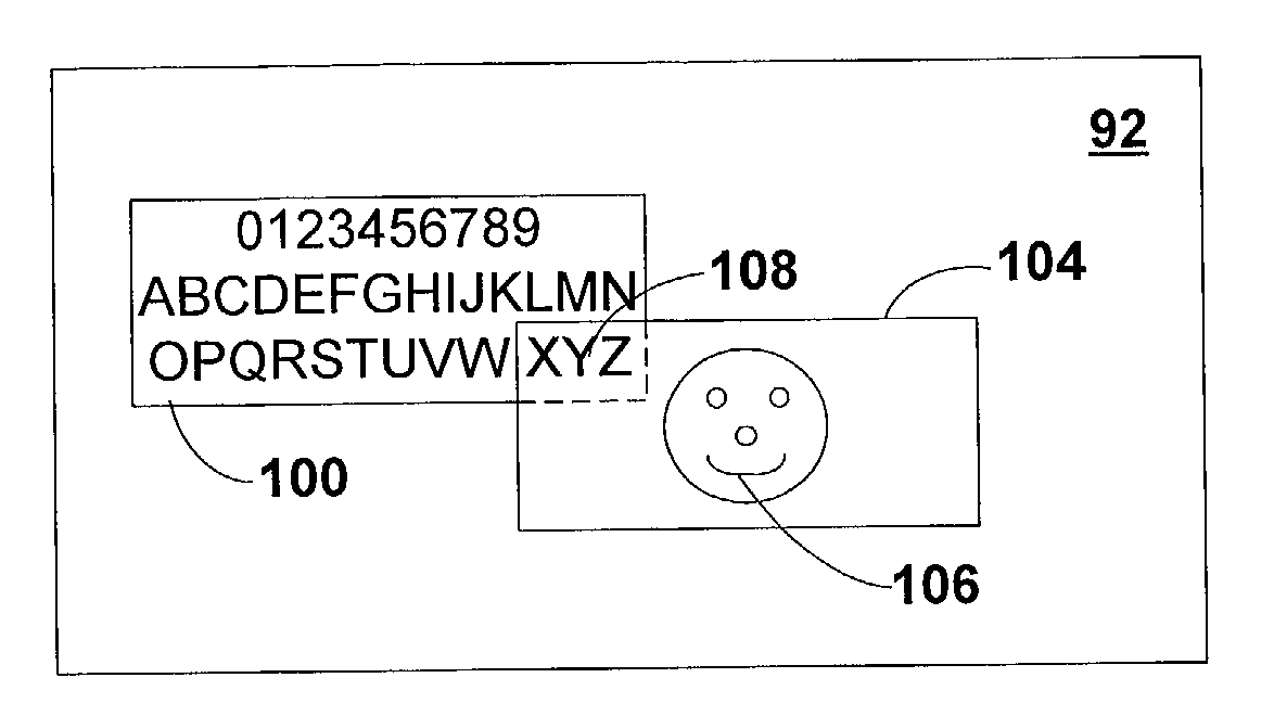
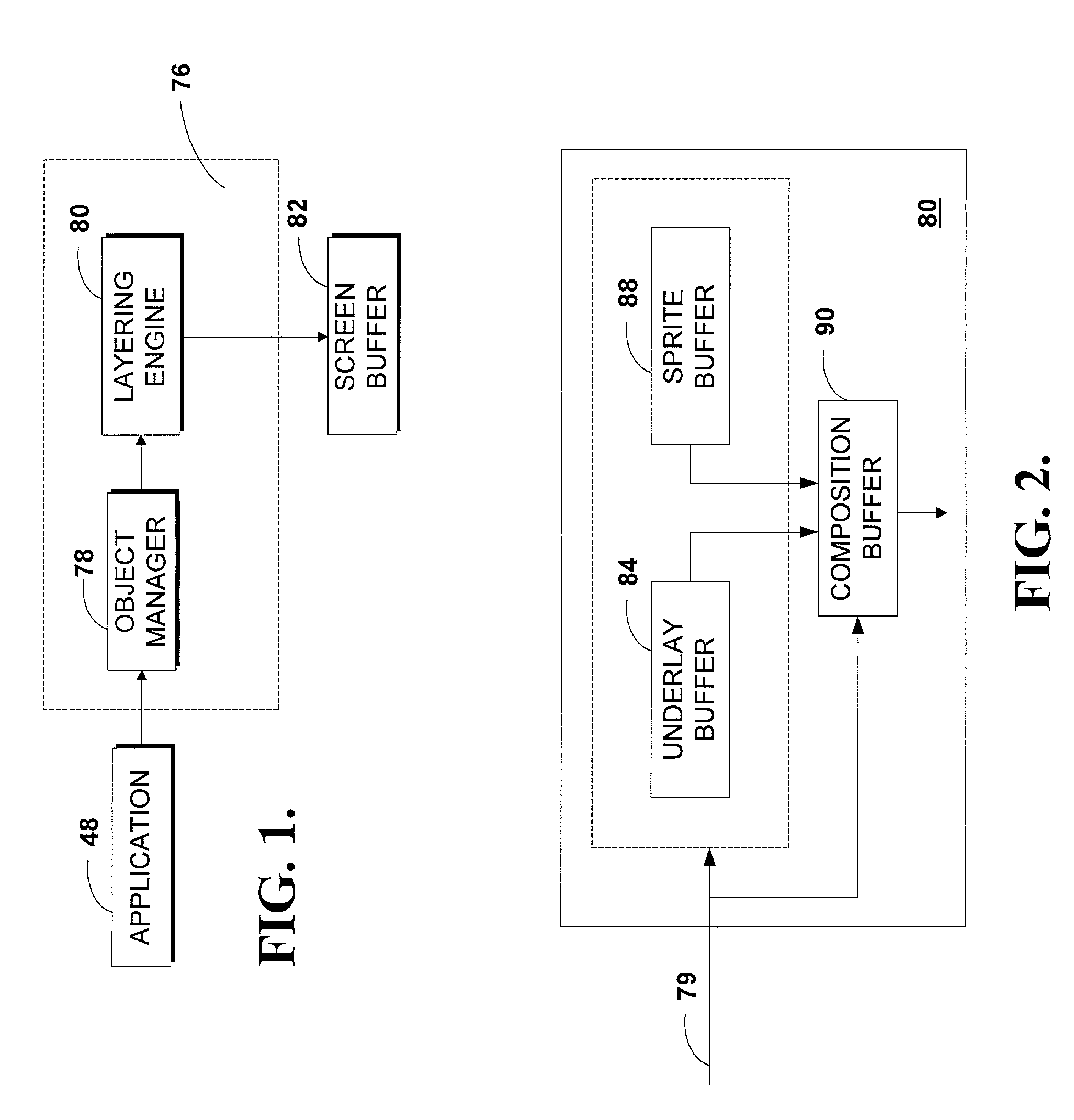
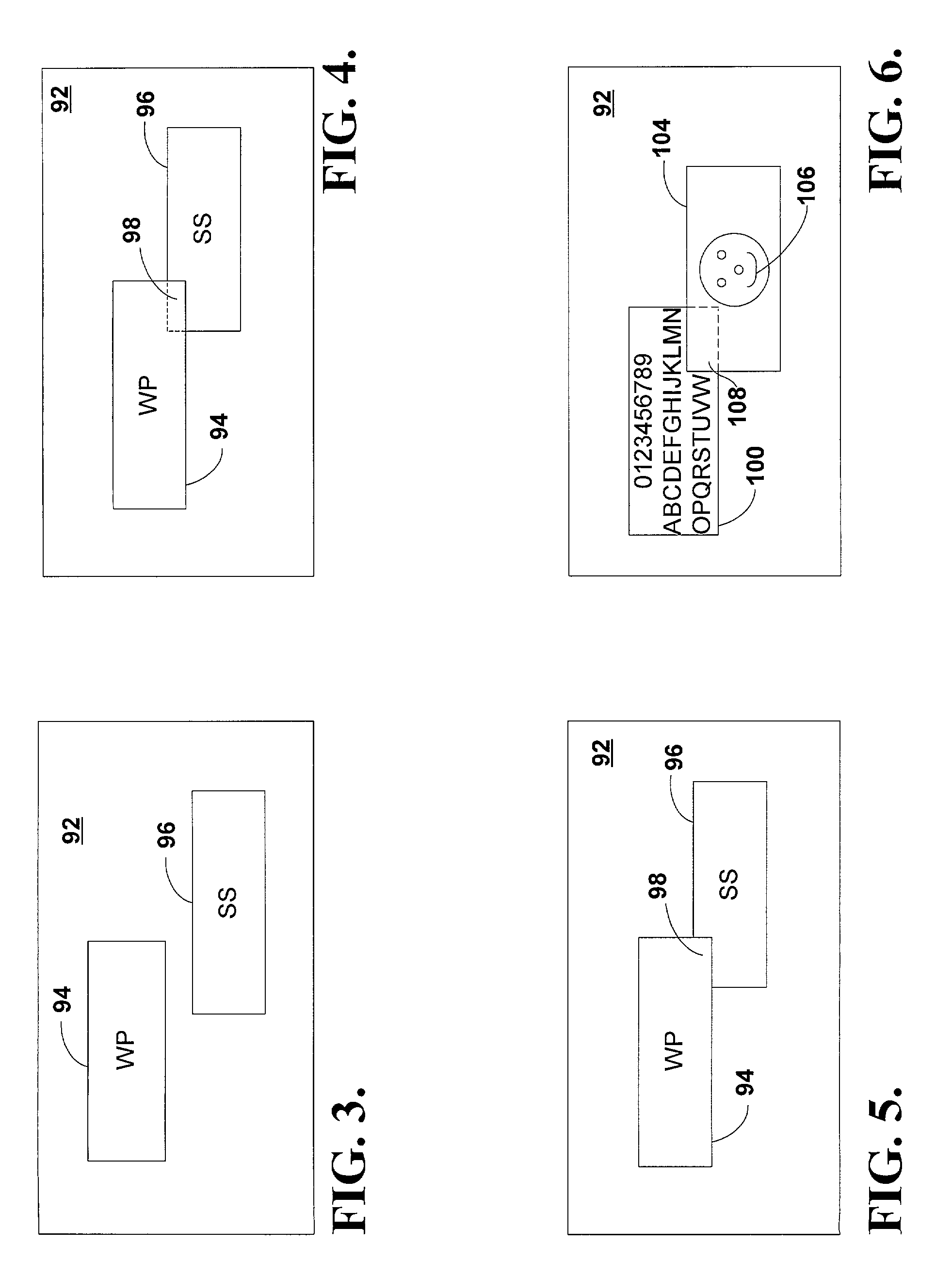
[0011]The present invention satisfies the above-described need by providing a layered object structure and method in which underlying display objects are blended with one or more layered objects.

Problems solved by technology

However, the user typically only views portions of the desired information in each application window if the application window is sized in its default display size.
However, the size of the information typically becomes sufficiently small that it is not easily understandable.
Although larger screen sizes or multiple monitors have been attempted to resolve this problem, these solutions are expensive and take up much physical space.
In addition, a change in an application window's z order would cause the contents of the window to rise ahead of other application windows possibly obscuring previously displayed windows.
Because the desktop typically includes background displays, such as the icons, inactive windows, and active windows, performance problems occur as windows are manipulated, such as by moving, resizing, or animating them.
However, because the second window is inactive, the regeneration would not have been required by the application and, consequently, wastes system resources.
Additionally, in terms of multiple moves, such as “dragging” a window across the screen or an animated window, this type of action often results in numerous window regenerations at great expense to the system resources.
Often, this not only reduces operating system performance, but also results in unwanted display flicker.
Another deficiency associated with conventional graphical operating systems is the requirement that each object displayed on the desktop be confined within a rectangular window.

Method used


Image

  • Method and structure for implementing a layered object windows
  • Method and structure for implementing a layered object windows
  • Method and structure for implementing a layered object windows

Examples


Embodiment Construction

[0039]The present invention provides a system and structure for implementing layered windows within a graphical operating environment. FIG. 17 illustrates an example of a suitable computing system environment in which the invention may be implemented. The computing system environment is only one example of a suitable computing environment and is not intended to suggest any limitation as to the scope of use or functionality of the invention. Neither should the computing environment be interpreted as having any dependency or requirement relating to any one or combination of components illustrated in the exemplary operating environment.

[0040]The invention is operational with numerous other general purpose or special purpose computing system environments or configurations. Examples of well known computing systems, environments, and / or configurations that may be suitable for use with the invention include, but are not limited to, personal computers, server computers, hand-held or laptop ...


PUM


Abstract

A display window is attributed a layering attribute such that underlying display windows are blended with the layered display window and displayed on the display screen. In a first embodiment, the layered window and the underlying window are represented as bitmaps. Any overlapping portions of the underlying window bitmap are redirected to an underlay buffer and composited with the layered window bitmap according to a display order and an opacity level. In a second embodiment, the layered window and the underlying window are represented as hardware sprites. Graphics device hardware stores copies of each sprite and composites each sprite according to a display order and an opacity level. In either embodiment or in a combination of both, as the layered window is moved or resized, the stored data allows for updating the composite display without requiring system expensive display regenerations.

Description

[0001]This application is entitled to priority pursuant to a provisional application filed Mar. 24, 1999, Ser. No. 60 / 126,002.TECHNICAL FIELD[0002]In general, the present invention relates to computer software, and more particularly, to a method and structure for implementing layered windows on a computer display screen.BACKGROUND OF THE INVENTION[0003]Personal computers (PCs) such as IBM-compatible PCs typically include hardware devices such as a processor and a memory for implementing various software programs, a principal one being a central operating environment. In turn, the operating environment, or operating system, supports the variety of other software applications such as a word processing program or a spreadsheet program.[0004]Some operating systems include a graphical user interface (GUI), described generally as a graphical operating system, which displays various information to the user as a combination of pictures and text that the user can manipulate. Generally, some ...

Claims


Application Information

Patent Timeline
Patent Type & Authority Patents(United States)
IPC IPC(8): G06F15/00G06F13/00
CPCG09G5/42G09G5/14G06F3/14G09G2340/10
Inventor GOOSSEN, J. ANDREWGOROKHOVSKY, VADIM
Owner MICROSOFT TECH LICENSING LLC
Why Eureka
Try Eureka