Mechanic's step with stirrup

a technology of mechanical steps and stirrups, which is applied in the direction of building scaffolds, transportation and packaging, building aids, etc., can solve the problems of limited tire sizes, user injury, and the inability of anderson invention to adjust to larger tires, so as to reduce the risk of injury, and reduce the effect of manufacturing cos

Inactive Publication Date: 2007-01-30
TAFOYA CRAIG A +2
View PDF16 Cites 19 Cited by
  • Summary
  • Abstract
  • Description
  • Claims
  • Application Information

AI Technical Summary

Benefits of technology

[0006]The primary object of this invention to provide a suspended step that can be used securely over the tire of a motor vehicle and can be broken down into sub-parts for compact storage. Another object of this invention is to provide a suspended step that is simple in design for cost efficient manufacture. It is a further object of this invention to provide a suspended step that has a stirrup below its step for added user convenience and ease of access to its step. It is also an object of this invention to provide a suspended step that has sturdy design and construction. A further object of this invention is to provide a suspended step that is easy and fast to assemble and disassemble.
[0007]The present invention, when properly made and used, will provide a step that can be securely fixed over the top of a vehicle tire for user access to the engine compartment for inspection, repair, and maintenance purposes, or access to the upper portions of high-profile vehicles for cleaning, inspection, access to roof-mounted luggage racks, and other purposes. It has a strong tubular closed-loop construction, with a step having two elongated lateral openings through which the frame is passed for a secure and non-slip positioning of the step during its use, as well as fast mounting and disassembly without fasteners directly secured between the step and the frame. The frame separates in four places for disassembly into four compactly storable sub-parts. Present invention frame separation also permits tire width adjustment and rapid step positioning during assembly. Although it is preferred for a pin and clip combination to be used for each connection of adjacent portions of the present invention closed loop frame, such a connection is not critical and, although not shown, it is also contemplated for other quick-release and non-slip fasteners or fastener assemblies to also be used. However, what ever fastener means is used, it should be easily removable by hand and without the use of tools. The portion of the frame extending front-to-back laterally under the step may also be adjustable in depth, so as to permit the use of steps with differing depth dimension. Although the stirrup height is not user adjustable, during manufacture various embodiments of the present invention may be given stirrups with differing height dimensions for special applications. Further, the present invention has an upper configuration that securely hooks over the top of a vehicle tire with a rear connecting member and cannot be dislodged from its usable position when a large weight / load is placed upon its step, and its strong closed-loop tubular structure resists parallelogram deforming while under load. The goal of low cost manufacture in the present invention is met by its simple design and the few parts needed. In addition, it is preferred for the present invention to have an elongated notch centrally in its rear surface configured to clear the lug nuts used to mount the vehicle wheel / tire in place. No other mechanic's step is known that has the same structure and features as the present invention, or all of its advantages.

Problems solved by technology

Also, the Anderson invention is not adjustable to larger tires, only limited tires sizes.
In addition, the Tans invention has no upper adjustability for differing tire widths and no stirrup below its step.
Further, the Tans invention step is attached via an interference fit to the frame, which can slip when it becomes worn and cause user injury.
Further, the Miller invention has no upper adjustability for differing tire widths and its structure is subject to parallelogram deforming while under load.

Method used


Image

  • Mechanic's step with stirrup
  • Mechanic's step with stirrup
  • Mechanic's step with stirrup

Examples


Embodiment Construction

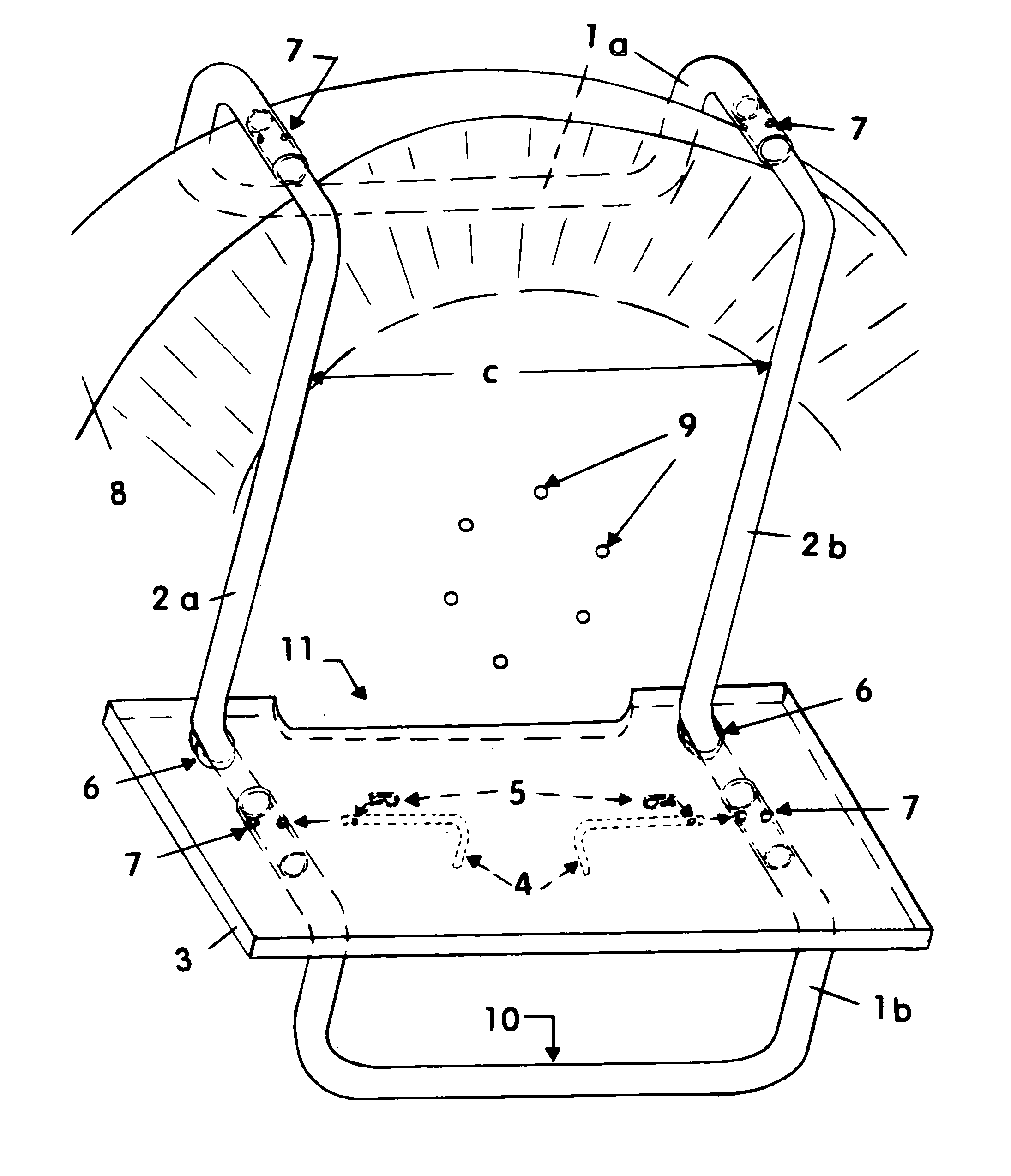
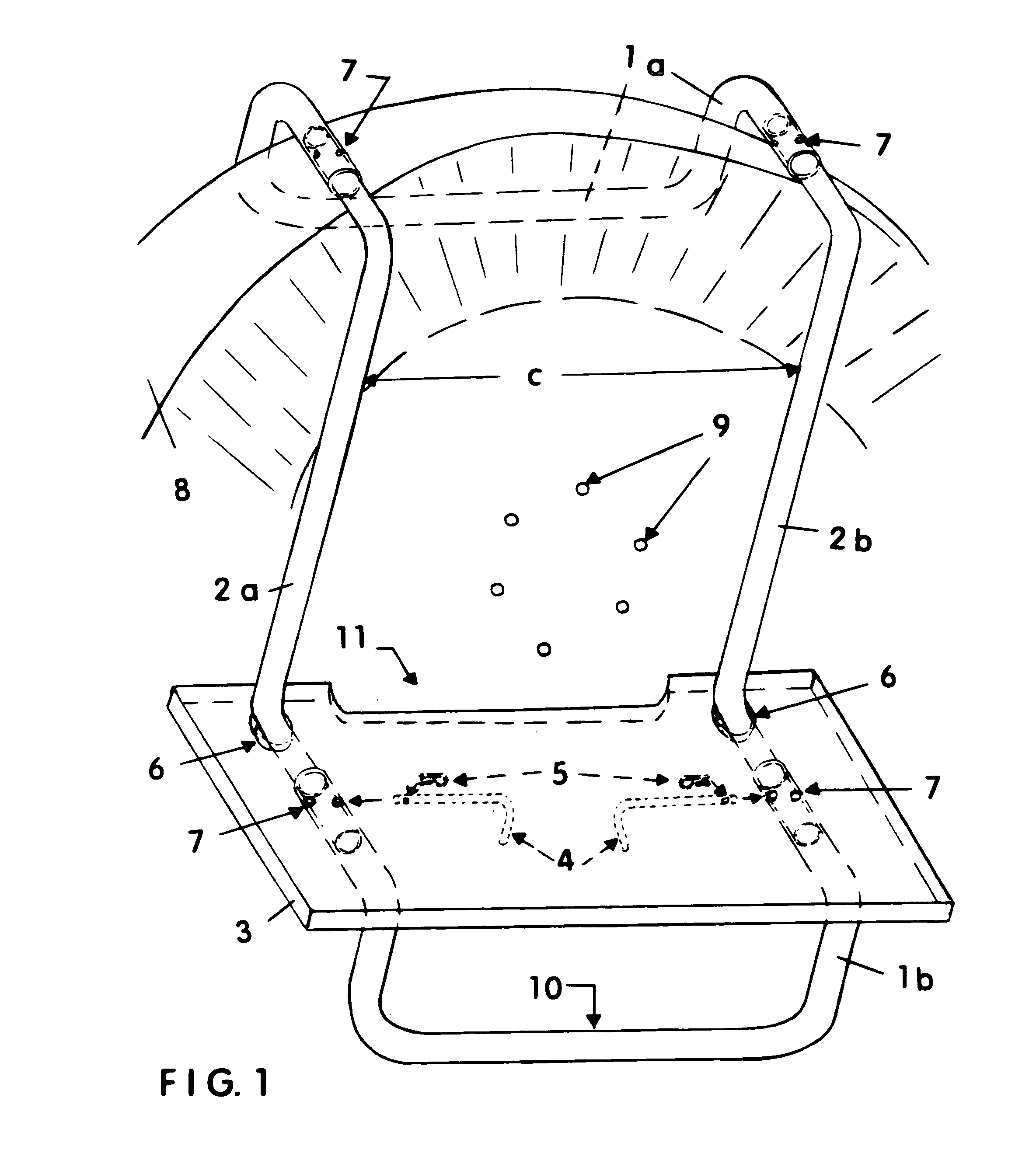
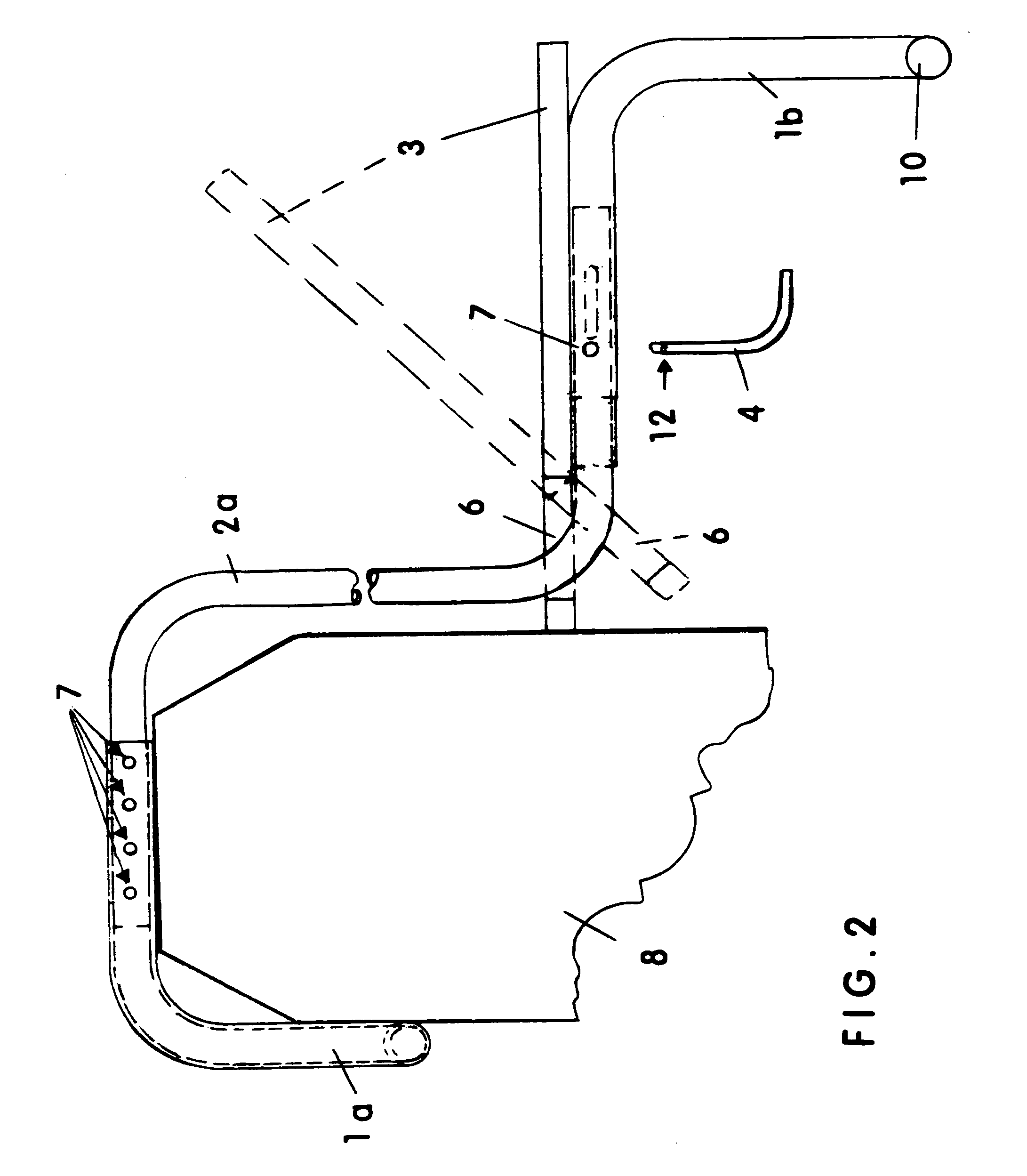
[0011]The present invention provides a suspended step 3 that is configured for attachment over the top of the tire 8 of a motor vehicle (not shown) and which can support a mechanic (not shown) working in the vehicle's engine compartment. It has a closed-loop tubular frame (components 1a, 1b, 2a, and 2b) that can be broken down into sub-parts for compact storage in the motor vehicle with which it is used. It further has top frame member 1a configuration with a rearwardly directed portion and a downwardly directly portion, separated by a right angle bend, that together securely hook the frame over a tire 8 and at least one pair of bores 7 therethrough on its rearwardly directed portion that permits the present invention to be adjustable to differing tire 8 widths. Also, a substantially vertically-extending left side frame member 2a downwardly depends from the top frame member 1a configuration, a substantially horizontally-extending right side frame member 2b downwardly depending from ...


PUM


Abstract

A suspended step assembly that is attachable over the tire of a motor vehicle and which can support a mechanic working in the engine compartment. It has a frame that can be broken down into sub-parts for compact storage in a motor vehicle, is easy and fast to assemble and disassemble, is adjustable to differing tire widths, has an upper configuration that securely hooks over the top of the tire, has a strong and simple closed-loop tubular structure that resists parallelogram deforming while under load, has a step that is secured into a fixed position on the frame without fasteners, and has a bottom stirrup under its step. Applications may include, but are not limited to, use by mechanics to more easily and efficiently perform engine work, and use by those needing to clean or otherwise have access to the upper portions of high-profile vehicles.

Description

CROSS-REFERENCES TO RELATED APPLICATIONS[0001]NoneBACKGROUND[0002]1. Field of the Invention[0003]This invention relates to the fields of seats, scaffold supports, and steps that can be suspended from the wheel of a motor vehicle, specifically to a suspended step and frame assembly that is attachable over the tire of a motor vehicle and which can support a mechanic during work in the engine compartment with the mechanics feet positioned approximately mid-tire. It can be broken down into sub-parts for compact storage in the motor vehicle with which it is used, and it is easy to assemble and disassemble. Quick-release fasteners allow for fast assembly and disassembly, as well as adjustability for differing tire widths and steps of differing depth dimension, as needed in differing applications. Further, the present invention has an upper configuration that can be securely hooked over the top of the tire by providing horizontal engagement with the rear surface of the tire, wherein the up...

Claims


Application Information

Patent Timeline
Patent Type & Authority Patents(United States)
IPC IPC(8): B60R3/00
CPCB60R3/007
Inventor TAFOYA, CRAIG A.TAFOYA, MARY ETAFOYA, SAMUEL BARRAN
Owner TAFOYA CRAIG A
Why Eureka
Try Eureka