
Sheet material dispenser with transfer system and method

a dispenser and transfer system technology, applied in the field of sheet material dispensers, can solve the problems of creating unique refilling problems for maintenance personnel, occupying a rather large volume, and a relatively expensive type of sheet material, and dispensers often require complicated transfer systems

Inactive Publication Date: 2007-01-30
GPCP IP HLDG LLC
View PDF39 Cites 58 Cited by
  • Summary
  • Abstract
  • Description
  • Claims
  • Application Information

AI Technical Summary

Benefits of technology

The present invention is a sheet material dispenser with a transfer system that can transfer dispensing from one mode to another mode. This allows for flexibility in dispensing from different sources of sheet material. The dispenser includes a housing with an outlet for dispensing sheet material, and a first rotatable roller and a second rotatable roller in the housing. The first roller has a recessed portion, and the second roller has a raised portion that aligns with the recessed portion. A biasing element or a driving mechanism can be used to transfer the dispensing from one mode to another mode. The invention also includes a method of dispensing sheet material from the first source to the second source. The technical effects of the invention include improved flexibility in dispensing from different sources of sheet material, and a more efficient and reliable transfer system.

Problems solved by technology

As a result, each source creates unique refilling problems for maintenance personnel.
Although most of these types of dispensers are relatively simple, there are drawbacks associated with using folded sheet material because this type of sheet material can be relatively expensive and occupy a rather large volume.
These dispensers often require complicated transfer systems to switch dispensing from one roll to another.
Both of these types of transfer systems, however, have complex transfer mechanisms and require a relatively long time to load the sheet material rolls.
As a result, maintenance personnel sometimes bypass the transfer system by only maintaining a single roll of sheet material in the dispenser.
This has the effect of increasing the number of maintenance checks.
Such practice can result in significant unnecessary waste of usable sheet material.

Method used


Image

  • Sheet material dispenser with transfer system and method
  • Sheet material dispenser with transfer system and method
  • Sheet material dispenser with transfer system and method

Examples


second embodiment

[0040]FIG. 9 is an isometric view of the invention including a lever actuating system; and

third embodiment

[0041]FIG. 10 is an isometric view of the invention including a motor driven system.

DESCRIPTION OF THE PREFERRED EMBODIMENTS

[0042]Reference will now be made in detail to the present exemplary embodiments of the invention, examples of which are illustrated in the accompanying drawings. Wherever possible, the same reference numbers will be used throughout the drawings to refer to the same or like parts.

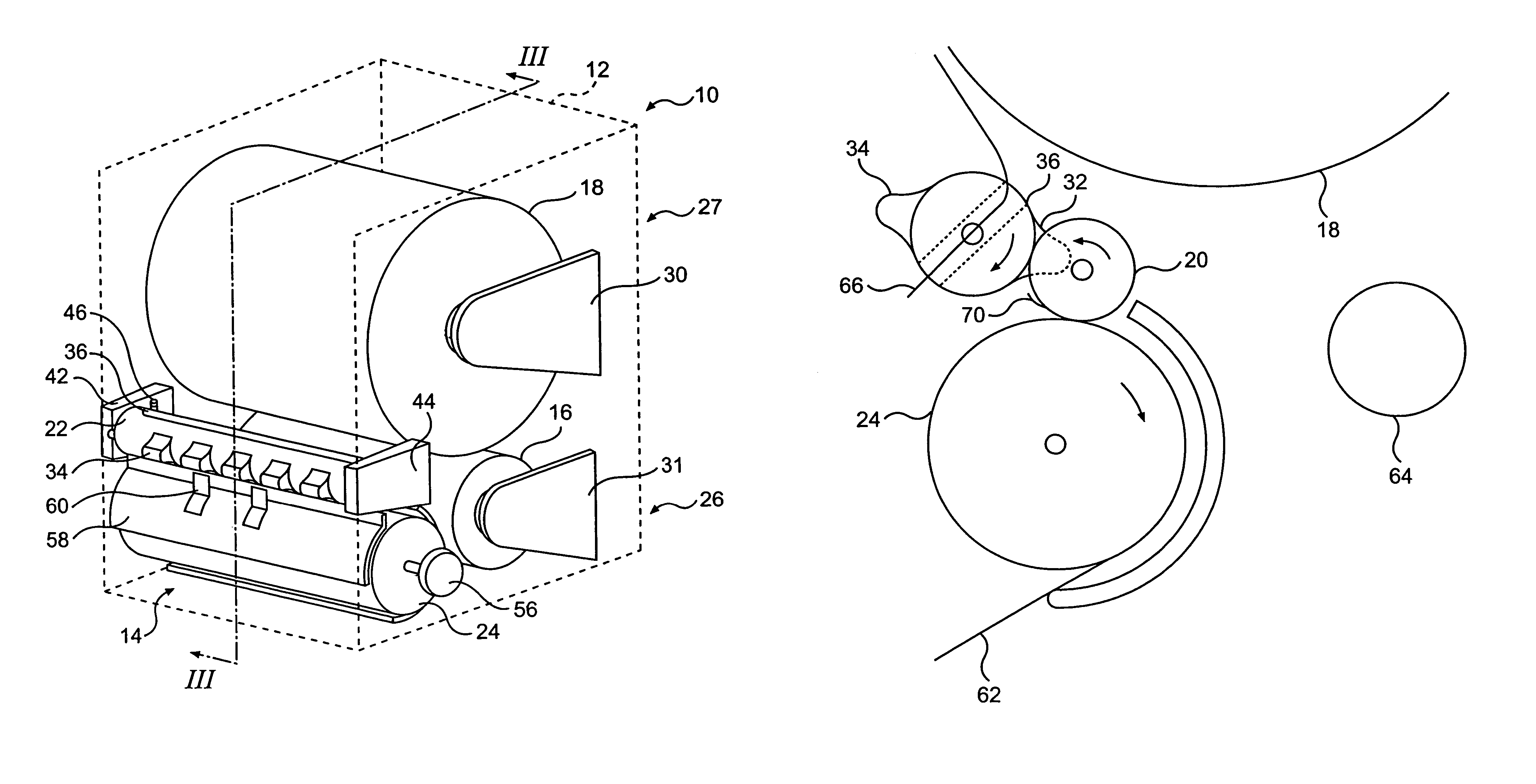
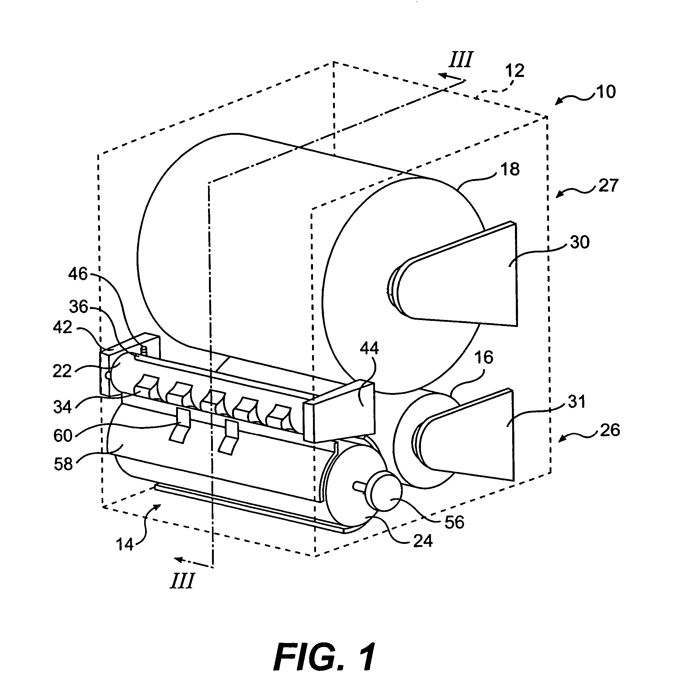
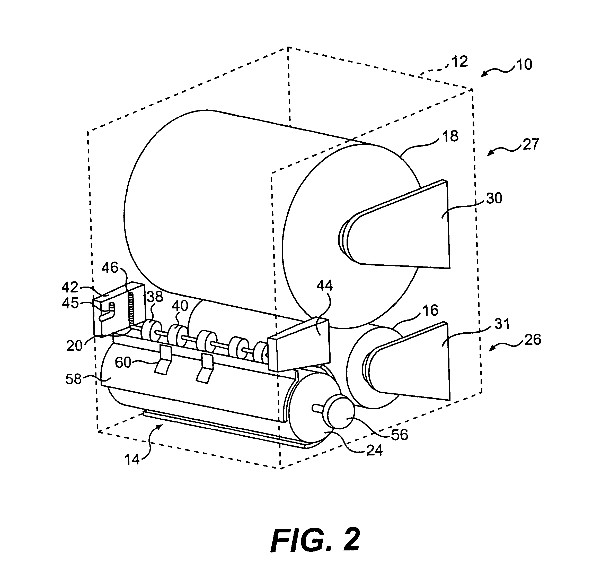
[0043]FIGS. 1–3 show an embodiment of a sheet material dispenser 10. The dispenser 10 includes a housing 12 having an outlet 14 and a cover (not shown). A first sheet material source 16 and a second sheet material source 18 are stored within the housing 12. A dispensing roller 20 and an optional cutting roller 24 cooperate to dispense sheet material from either the first source 16 or second source 18 through the outlet 14. A transfer roller 22 cooperates with the dispensing roller 20 to transfer dispensing from a first mode wherein sheet material is dispensed from the first source 16 to...

first embodiment

[0049]In the first embodiment, the cutting roller 24 is rotated as the sheet is pulled from the dispenser, as it is preferred that the driving force for activation of the mechanism is provided by the tension exerted on the sheet as the user draws it from the dispenser. Dispensers so configured are usually referred to as “touchless”. An optional driving mechanism 56 is provided to rotate the cutting roller 24. In the embodiment of FIGS. 1–3, the driving mechanism 56 is a rotatable knob, which in touchless configurations would serve as an emergency feed. Alternatively, the driving mechanism could be a push lever, or an electric motor, which will be described below.

[0050]A shield 58 is arranged to prevent sheet material from the second source 18 from coming into contact with the cutting roller 24 before the transfer roller 22 transfers dispensing to a mode wherein sheet material is dispensed from the second source 18. Mounted to the shield 58 are a plurality of fingers 60, which also a...


PUM

PropertyMeasurementUnit
coefficient of frictionaaaaaaaaaa
volumeaaaaaaaaaa
tensionaaaaaaaaaa

Abstract

A dispenser having a transfer mechanism for transferring between a first source and a second source of sheet material, and a method for transferring between the first source and the second source. Dispensing is transferred from a first source to a second source upon an absence of sheet material from the first source. The transfer mechanism includes a transfer roller with a slot to receive a free end of sheet material from the second source. The transfer roller also includes a plurality of raised portions, the raised portions are free to rotate through a dispensing roller when there is an absence of sheet material from the first source. This rotation introduces the free end of sheet material from the second source to the dispensing roller, and allows dispensing from the second source. Afterwards, the transfer roller is set to receive sheet material from a new source of sheet material.

Description

[0001]This application is a divisional application of U.S. application Ser. No. 09 / 736,419, filed Dec. 15, 2000, U.S. Pat. No. 6,826,985 which is incorporated herein by reference.DESCRIPTION OF THE INVENTIONField of the Invention[0002]The present invention relates to sheet material dispensers in general. More particularly, the present invention relates to sheet material dispensers capable of transferring dispensing from a first mode wherein sheet material is dispensed from a first sheet material supply to a second mode wherein sheet material is dispensed from a second sheet material supply, and a method of transfer.BACKGROUND OF THE INVENTION[0003]Sheet material dispensers are designed to dispense sheet material from various sources including folded sheet material and rolled sheet material. Each type of sheet material source requires a different means of loading and dispensing the sheet material. As a result, each source creates unique refilling problems for maintenance personnel.[0...

Claims


Application Information

Patent Timeline
Patent Type & Authority Patents(United States)
IPC IPC(8): B26F3/00A47K10/36B65H35/08
CPCA47K10/36B65H35/08Y10S83/949A47K10/3631A47K10/3612A47K10/3687A47K2010/3681Y10T83/04Y10T83/4812Y10T83/4815Y10T83/6636Y10T83/902Y10T225/10Y10T225/211Y10T225/232Y10T225/282Y10T225/393
Inventor BROEHL, JOSHUA M.
Owner GPCP IP HLDG LLC
Learn More