Flexible finishing shoe

a flexible, shoe technology, applied in the direction of gear teeth, superfinishing machines, gear teeth, etc., can solve the problems of insufficient manual finishing operations, material and labor losses of machinists, failures at one or more grinding areas or abrasive tape positions,

Inactive Publication Date: 2007-01-30
BARTON II KENNETH A
View PDF5 Cites 10 Cited by
  • Summary
  • Abstract
  • Description
  • Claims
  • Application Information

AI Technical Summary

Benefits of technology

[0008]The flexible finishing shoe of the present invention has been developed to meet the need for a surface finishing shoe that is able to adequately and consistently finish the transition from a crankshaft bearing surface outside diameter to the raduised portion.

Problems solved by technology

As is common in large scale production, failures may occur at one or more of the grinding areas or abrasive tape positions.
Because microfinishing is the final stage in surface treatment operations, i.e. after rough grinding and grinding, the scrapping of microfinished parts results in a substantial loss of both material and labor to the machinist.
It is generally recognized in the industry that these manual finishing operations are inadequate for achieving finished surfaces of standard quality.
Programmably controlling a finishing machine to accept each individual workpiece that requires microfinishing from different internal combustion engines is uneconomical and inefficient.

Method used


Image

  • Flexible finishing shoe
  • Flexible finishing shoe
  • Flexible finishing shoe

Examples


Embodiment Construction

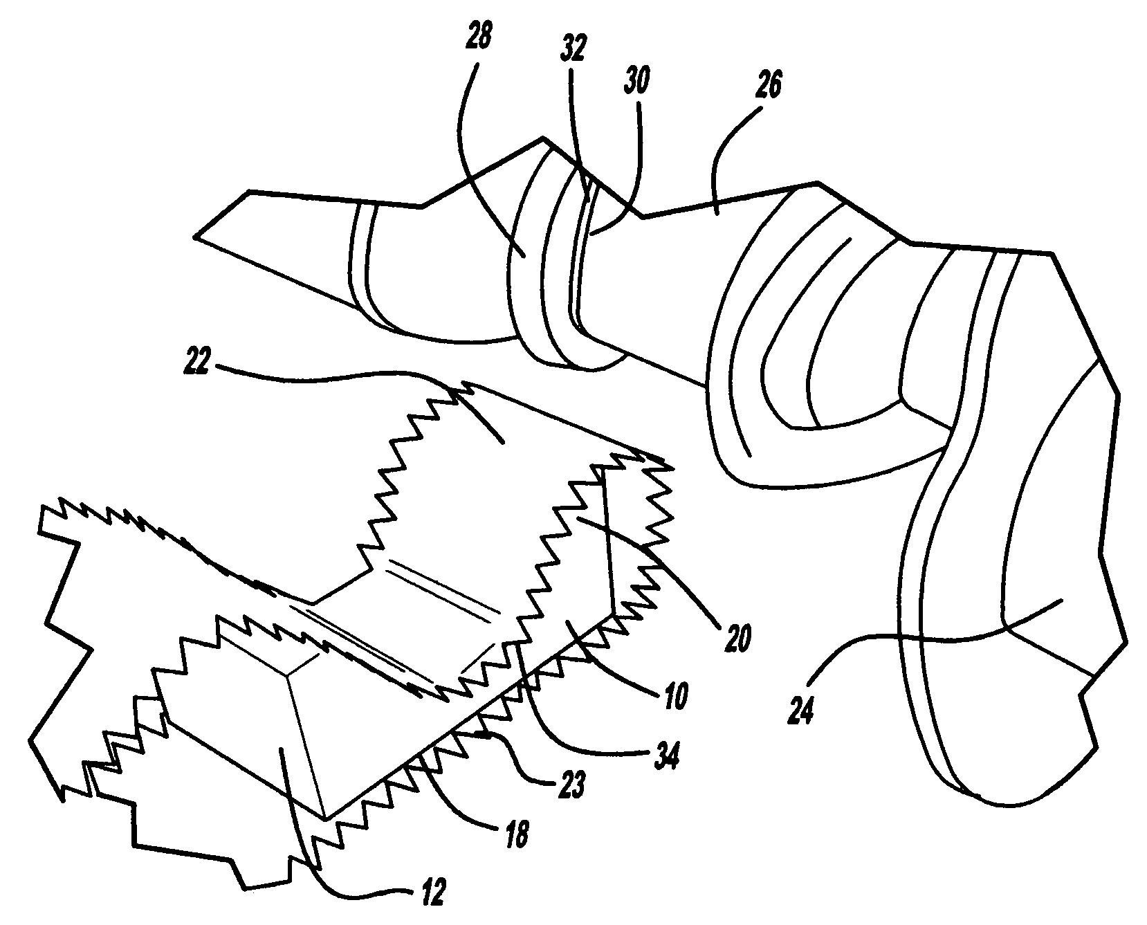
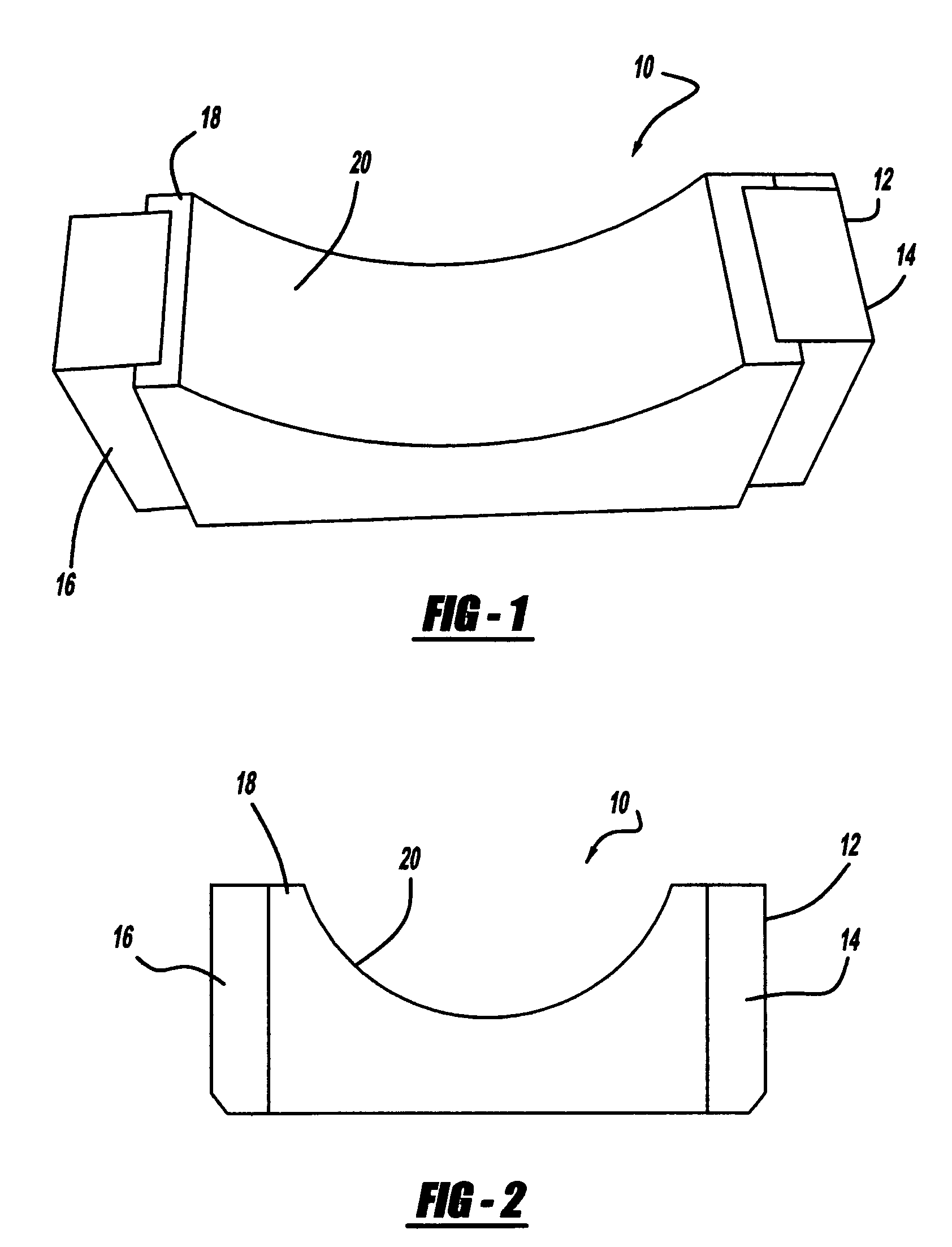
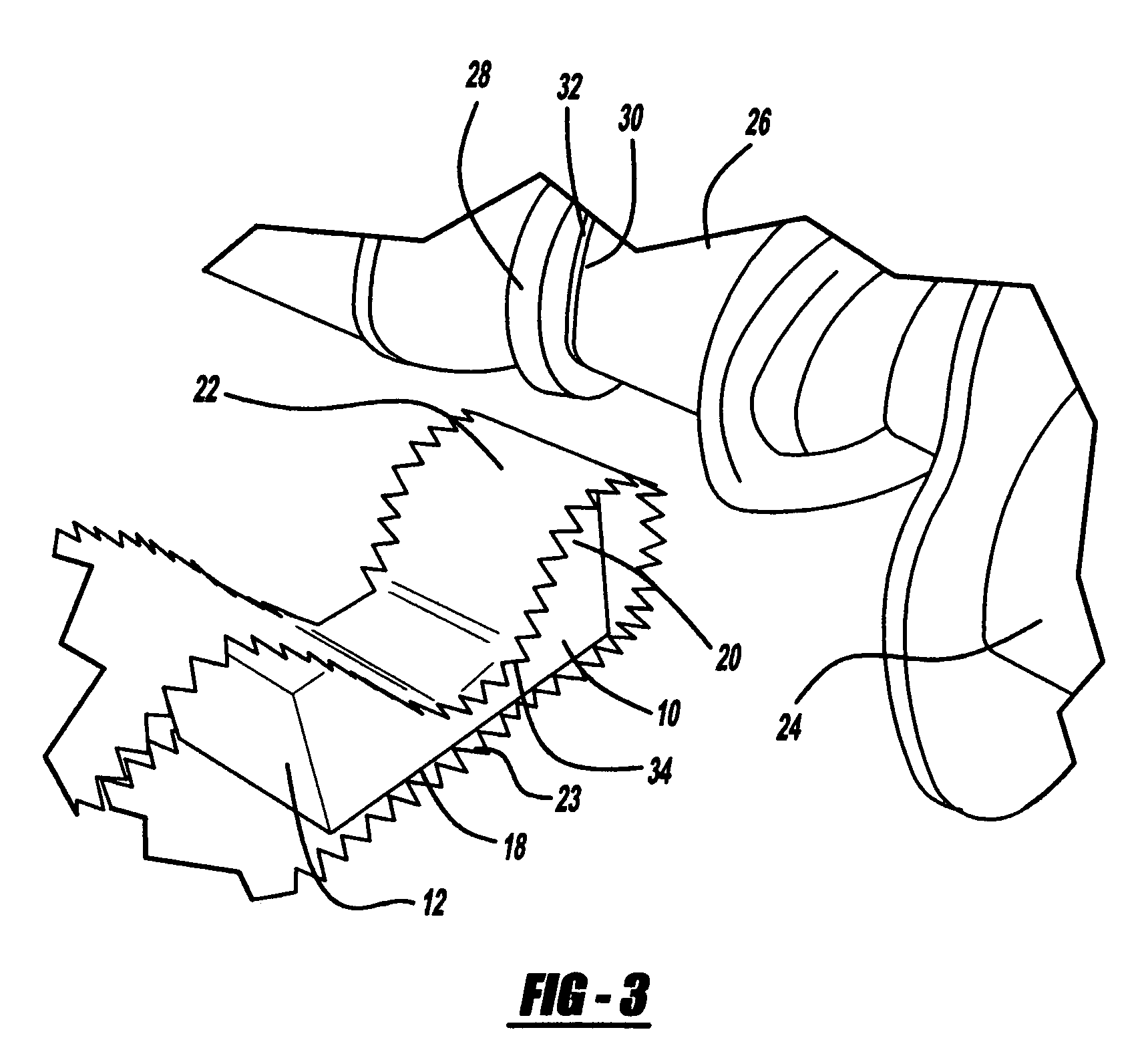
[0018]Referring now to FIG. 1, there is shown a flexible finishing shoe 10. Flexible finishing show 10 includes a shoe base 12 having a first side 14 and an opposing second side 16. A finishing body 18 is disposed between first side 14 and an opposing second side 16. Finishing body 18, in the preferred embodiment, is manufactured from a flexible non metallic material. While not limiting the present invention, it is contemplated by the present invention to manufacture the finishing body from a urethane material with a hardness is a range form 30 to 95 durometer.

[0019]The finishing body 18 is insert molded onto the shoe base 12 in the preferred embodiment. Other forms of attachment such as use of adhesive or mechanical means such as screw attachments and rivet-like attachments may also be used. Referring to FIGS. 1 and 2, it is shown that the finishing body 18 has a contact surface 20. This contact surface 20 is semi-circular is cross section and generally matches or conforms to the s...


PUM

PropertyMeasurementUnit
flexibleaaaaaaaaaa
hardnessaaaaaaaaaa
circumferenceaaaaaaaaaa

Abstract

A flexible finishing shoe for finishing a workpiece have a bearing surface and an adjacent side, the flexible finishing shoe comprising a shoe base having a first side and an opposing second side and a finishing body disposed between the first and second sides, the finishing body made from a flexible non-metallic material capable of conforming to the bearing surface and adjacent side.

Description

TECHNICAL FIELD[0001]This invention relates generally to a flexible finishing shoe for a finishing arm and more particularly to a flexible finishing shoe which is capable of conforming to any workpiece surface shape.BACKGROUND OF THE INVENTION[0002]“Microfinishing” or “superfinishing”, as it is known in the art, is a surface finishing process wherein a grinding means is brought to bear against a workpiece which has been previously rough ground. Microfinishing is a low velocity abrading process which generally follows rough grinding. Because microfinishing incorporates lower cutting speeds than grinding, heat and pressure variants may be minimized to provide improved size and geometry control. Those skilled in the art recognize that surface quality or roughness is measured in roughness average values (Ra) wherein Ra is the arithmetical average deviation of minute surface irregularities from hypothetical perfect surfaces. Microfinishing can provide surface quality of approximately 1 t...

Claims


Application Information

Patent Timeline
Patent Type & Authority Patents(United States)
IPC IPC(8): B24B1/00B24B49/00
CPCB24B5/42B24B19/12B24B35/00B24B21/08B24B21/004
Inventor BARTON, II, KENNETH A.
Owner BARTON II KENNETH A
Why Eureka
Try Eureka