Superconductive magnet including a cryocooler coldhead

a superconductive magnet and cryocooler technology, applied in the field of superconductive magnets, can solve the problems that significantly affect the operation cost of the mri system, and achieve the effect of reducing the boiloff rate of cryogen gas and reducing radiation heat load

Active Publication Date: 2007-01-30
GENERAL ELECTRIC CO
View PDF7 Cites 42 Cited by
  • Summary
  • Abstract
  • Description
  • Claims
  • Application Information

AI Technical Summary

Benefits of technology

[0009]Further embodiments of the invention provide a method to reduce boiloff rate of cryogen gas during a coldhead failure or power off condition in a zero boiloff cryogen cooled recondensing superconducting magnet assembly including superconducting magnet coils suitable for magnetic resonance imaging. The method includes disposing a liquid cryogen in a cryogen pressure vessel to provide cryogenic temperatures to the magnet coils for superconducting operation; surrounding the pressure vessel with a vacuum vessel spaced from the pressure vessel; surrounding the pressure vessel with a first thermal shield spaced from the pressure vessel; surrounding the first thermal shield with a second thermal shield spaced from the first thermal shield, the second thermal shield intermediate the vacuum vessel and the first shield; thermally connecting a cryocooler by a first and a second thermal interface to the first and second thermal shields, respectively; positioning a recondenser in the space between the pressure vessel and the first thermal shield and thermally connected by a thermal interface to the cryocooler to recondense, back to liquid, cryogen gas provided from the pressure vessel; and returning the recondensed liquid cryogen to the pressure vessel; wherein the second thermal shield surrounding the first thermal shield reduces a radiation heat load from the first thermal shield to the pressure vessel lowering boiloff of cryogen gas under conditions of failure or power off of the cryocooler.
[0010]Yet another embodiment of the invention provides for a zero boiloff liquid helium cooled recondensing superconducting magnet assembly suitable for magnetic resonance imaging including a helium pressure vessel to contain a liquid helium reservoir to provide cryogenic temperatures to the magnet resonance imaging magnet assembly for superconducting operation; a vacuum vessel surrounding the pressure vessel and spaced from the pressure vessel; a first thermal shield surrounding the pressure vessel and spaced from the pressure vessel; a second thermal shield surrounding the first thermal shield and spaced from the first thermal shield, the second thermal shield intermediate the vacuum vessel and the first shield; and a recondenser and a cryocooler for cooling the recondenser to recondense helium gas formed in the pressure vessel back to liquid helium, the cryocooler thermally connected by a first and a second thermal interface to the first and second thermal shields, respectively; wherein the second thermal shield surrounding the first thermal shield reduces a radiation heat load from the first thermal shield to the pressure vessel lowering boiloff of helium gas under conditions of failure or power off of the cryocooler.

Problems solved by technology

Cryogens such as liquid helium, however, are not abundant and therefore can significantly impact the cost of operation of the MRI system.
However, when the cryocooler coldhead extending through a penetration to the liquid-helium vessel is not operational due to power off, coldhead failure or transportation, the coldhead acts as a heat source and adds significant heat into the cryostat.

Method used


Image

  • Superconductive magnet including a cryocooler coldhead
  • Superconductive magnet including a cryocooler coldhead
  • Superconductive magnet including a cryocooler coldhead

Examples


Embodiment Construction

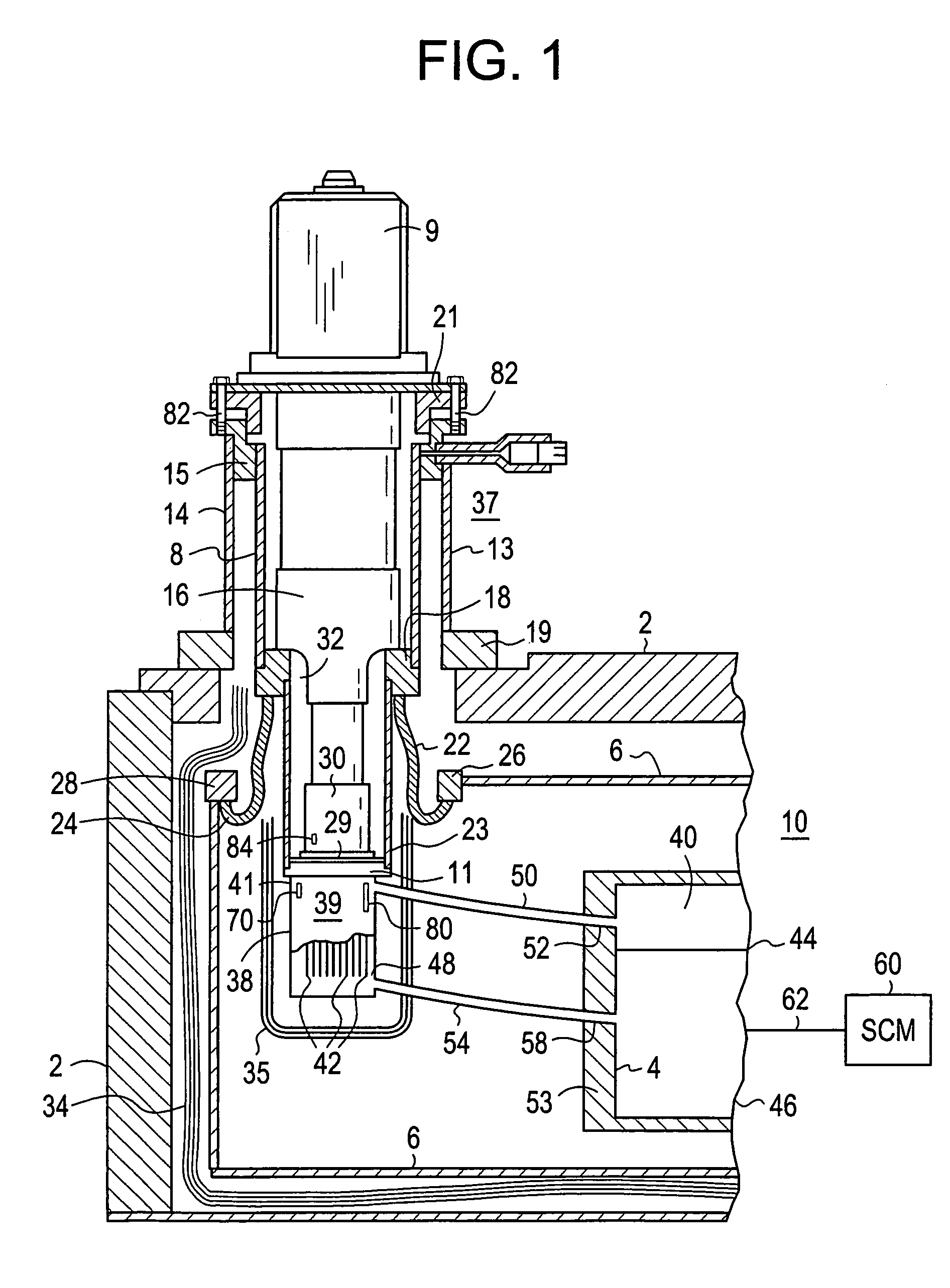
[0018]Referring first to FIG. 1, a current MRI magnet system 10 includes helium pressure vessel 4 including a liquid cryogen such as helium surrounded by vacuum vessel 2 with thermally isolating radiation shield 6 interposed between the helium vessel and the vacuum vessel. A cryocooler 12 (which may be a Gifford-Mahon cryocooler) extends through vacuum vessel 2 within sleeve 8 such that the cold end of the cryocooler may be selectively positioned within the sleeve without destroying the vacuum within vacuum vessel 2, and heat generated by motor 9 of the cryocooler is outside the vacuum vessel. External cryocooler sleeve ring 14 extends outside vacuum vessel 2, and collar 19 and sleeve flange 15 enable the securing of outer cryocooler sleeve 13 to vacuum vessel 2. Cryocooler 12 is installed in the cryocooler sleeve assembly 8, 18, 23 with matching transition flange 21 and secured with bolts 82 and associated washers.

[0019]First stage heat station 16 of cryocooler 12 contacts copper f...


PUM

PropertyMeasurementUnit
cryogenic temperaturesaaaaaaaaaa
pressureaaaaaaaaaa
superconductingaaaaaaaaaa

Abstract

A zero boiloff cryogen cooled recondensing superconducting magnet assembly including superconducting magnet coils suitable for magnetic resonance imaging including a cryogen pressure vessel to contain a liquid cryogen reservoir to provide cryogenic temperatures to the magnet coils for superconducting operation; a vacuum vessel surrounding the pressure vessel and spaced therefrom; a first thermal shield surrounding and spaced from the pressure vessel; a second thermal shield surrounding and spaced from the first thermal shield and intermediate the vacuum vessel and the first shield; a cryocooler thermally connected by a first and a second thermal interface to the first and second thermal shields, respectively; a recondenser positioned in the space between the pressure vessel and the first thermal shield and thermally connected by a thermal interface to the cryocooler to recondense, back to liquid, cryogen gas provided from the pressure vessel; and means for returning the recondensed liquid cryogen the pressure vessel; wherein the second thermal shield surrounding the first thermal shield reduces a radiation heat load from the first thermal shield to the pressure vessel lowering boiloff of cryogen gas under conditions of failure or power off of the cryocooler.

Description

BACKGROUND OF THE INVENTION[0001]The present disclosure relates generally to superconductive magnets, and more particularly to a superconductive magnet having a cryocooler coldhead.[0002]Magnets include resistive and superconductive magnets which are part of a magnetic resonance imaging (MRI) system used in various applications such as medical diagnostics. Known superconductive magnets include liquid-helium-cooled, cryocooler-cooled, and hybrid-cooled superconductive magnets. Typically, the superconductive coil assembly includes a superconductive main coil surrounded by a thermal shield surrounded by a vacuum enclosure. A cryocooler-cooled magnet typically also includes a cryocooler coldhead externally mounted to the vacuum enclosure, having its first stage in solid conduction thermal contact with the thermal shield, and having its second stage in solid conduction thermal contact with the superconductive main coil. A liquid-helium-cooled magnet typically also includes a liquid-heliu...

Claims


Application Information

Patent Timeline
Patent Type & Authority Patents(United States)
IPC IPC(8): F25B19/00H01F5/00
CPCH01F6/04G01R33/3815F25D19/006F25B9/14F25B2400/17
Inventor JIANG, LONGZHILEHMANN, GREGORY ALANLEGALL, EDWIN LAWRENCE
Owner GENERAL ELECTRIC CO
Why Eureka
Try Eureka