Dynamic-Pressure Bearing Device and Disk Drive

Active Publication Date: 2005-04-28
NIDEC CORP
View PDF12 Cites 16 Cited by
  • Summary
  • Abstract
  • Description
  • Claims
  • Application Information

AI Technical Summary

Benefits of technology

[0007] An object of the present invention is to make available a dynamic-pressure bearing device utilizing a lubricating fluid whose evaporation rate is low, and whose relative viscosity is c

Problems solved by technology

And changes in the characteristics due to moisture

Method used


Image

  • Dynamic-Pressure Bearing Device and Disk Drive
  • Dynamic-Pressure Bearing Device and Disk Drive
  • Dynamic-Pressure Bearing Device and Disk Drive

Examples


modification example 1

[0060] Although the invention created by the present inventors has been specifically explained based on modes of embodying the invention, it is not limited to the foregoing embodiments, in that various modifications are possible within a scope that does not deviate from the gist of the present invention.

[0061] In each of the respective Embodiments 1 through 3 described above, the sleeve is formed out of a metal component material such as phosphor bronze, but forming the sleeve from a synthetic polymer substance is also possible. In an implementation in which ionic liquid is utilized as the dynamic-pressure fluid, if the associated metal components are put into a relationship in which they differ from each other in substance—as would be the case, for example, with the shaft piece being stainless steel and the sleeve being phosphor bronze—corrosion could arise from an electric-potential difference between the two components being produced, which would be a cause of rust and similar p...

modification example 2

[0068] When selecting the substances that constitute the shaft piece and the sleeve, having the entire shaft piece or the entire sleeve be of the same base material is not absolutely essential. One way to do this is to form—by, for example, electroless nickel plating as aforementioned—a layer of a separate material onto the surface alone, to cover the surface in its entirety with a separate material. Moreover, it is not necessary that the region with the separate material be the entire surface.

[0069] Fairly peculiar phenomena such as crevice corrosion aside, corrosive reactions are most vigorous in the vicinity of the boundary surface(s), where the supply of oxygen is most abundant. Thus, as far as anti-corrosion measures to be taken in a dynamic-pressure bearing device in which ionic liquid is utilized are concerned, the vicinity of the boundary surface(s) is the critical area. Inasmuch as the supply of oxygen is relatively slight in the regions lying away from the boundary surfac...


PUM


Abstract

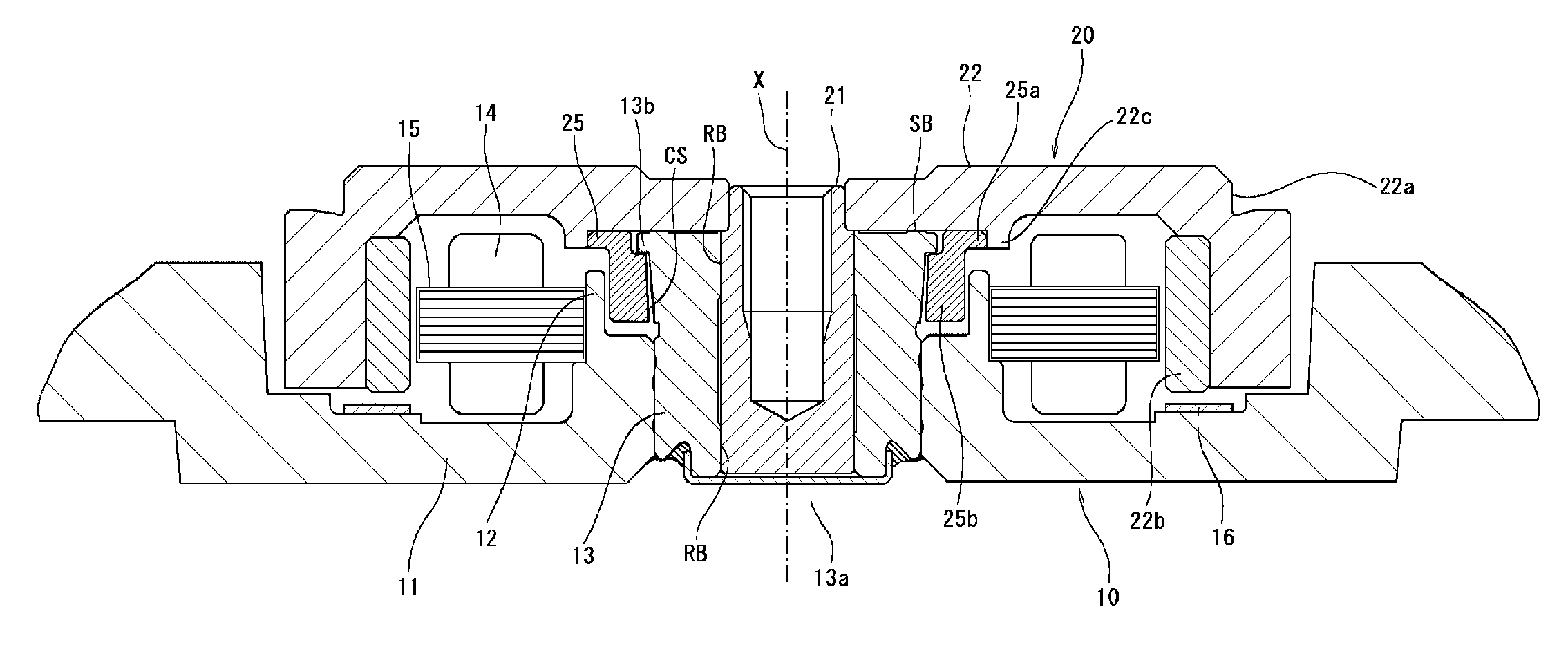
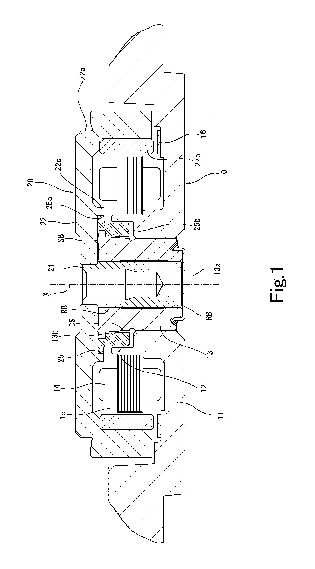
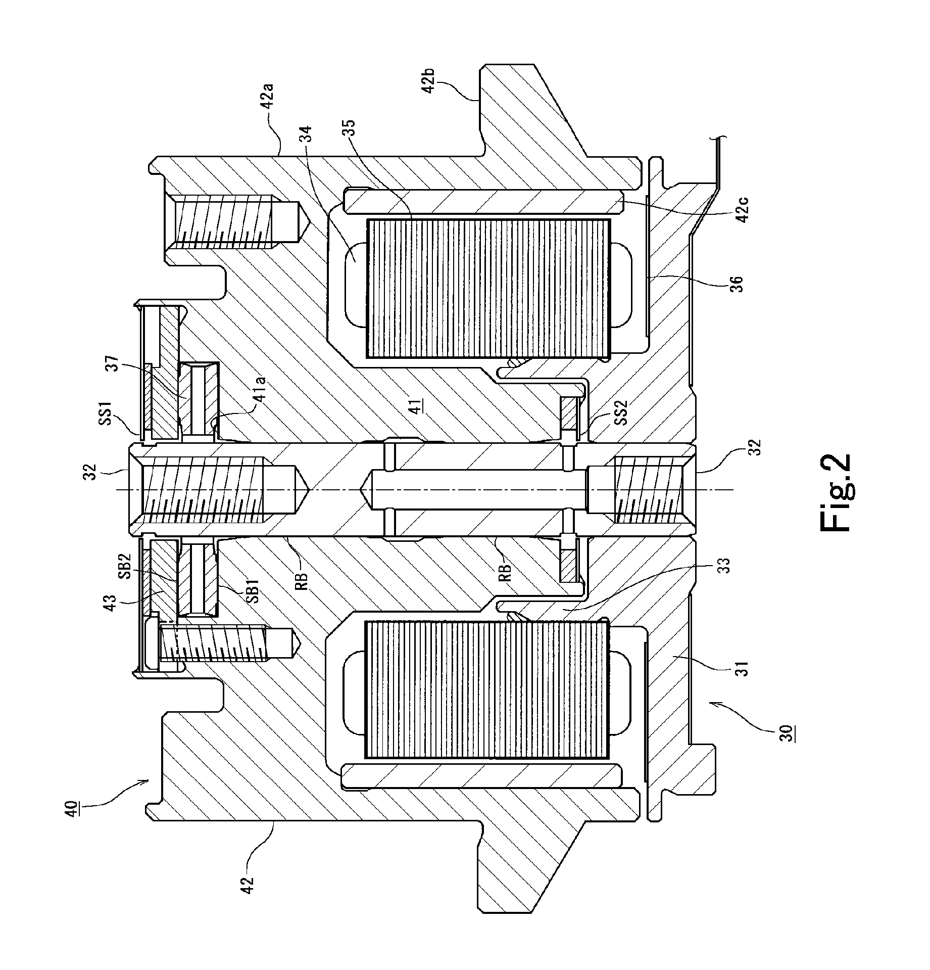
An ionic liquid is utilized as the dynamic-pressure fluid charged inside a bearing space formed in the gap where an axial bushing (axial component) [21] and a bearing sleeve (bearing component) [13] oppose. Designing a dynamic-pressure bearing device is made possible virtually without having to consider such factors as how to control dynamic-pressure-fluid evaporation or how to secure electrical continuity between the axial bushing and the bearing sleeve. Owing to ionic liquids' property of not hydrolyzing, deterioration of the dynamic-pressure fluid from moisture absorption, oxidation, etc. is inhibited, yielding a dynamic-pressure bearing device with a long lifespan.

Description

BACKGROUND OF THE INVENTION [0001] 1. Technical Field [0002] The present invention relates to a dynamic-pressure bearing device having a configuration in which an ionic liquid is charged into a bearing space formed in between a shaft piece and a sleeve. The present invention relates further to a disk drive in which such a dynamic-pressure bearing device is installed, and to a method of keeping such a dynamic-pressure bearing device in storage. [0003] 2. Description of the Related Art [0004] The development of dynamic-pressure bearing devices capable of supporting various rotary components stably even under high-rpm operating conditions has been progressing in recent years. In dynamic-pressure bearing devices the sleeve part and the shaft piece, which is inserted into the sleeve part with the one being rotatable relative to the other, are each furnished with dynamic-pressure surfaces, and the bearing devices are configured with the sleeve-section dynamic-pressure surfaces arranged op...

Claims


Application Information

Patent Timeline
IPC IPC(8): F16C17/10F16C33/10F16C33/20F16C33/24G11B17/02G11B17/022G11B25/04G11B33/12H02K7/08
CPCF16C17/026F16C17/105F16C33/10G11B33/121G11B17/022G11B25/043F16C33/107F16C2370/12
Inventor GOMYO, MASATOSAICHI, MASAYOSHI
Owner NIDEC CORP
Why Eureka
Try Eureka