Method for reconfiguring a cryostat configuration for recirculation cooling

a cryostat and configuration technology, applied in refrigeration devices, superconducting magnets/coils, lighting and heating apparatus, etc., can solve the problem that no expert in this field has considered using refrigerators of this type in closed cooling circuits, and achieves low maintenance and operation costs, prolonging the refill interval of liquid helium, and high capacity utilization rate

Active Publication Date: 2015-01-08
BRUKER SWITZERLAND AG
View PDF7 Cites 17 Cited by
  • Summary
  • Abstract
  • Description
  • Claims
  • Application Information

AI Technical Summary

Benefits of technology

[0022]One possibility of reducing the evaporation rate of liquid helium from the first container is obtained in a very simple fashion by reducing the temperature of the second container (with respect to the previously normal temperature level of liquid nitrogen). By converting the second container to cooling by means of a different cooling fluid which has a substantially lower boiling point than nitrogen, the evaporation rate of helium from the first container can be reduced to considerably lower values (e.g. 50% of the normal value) since the cooling medium is in good thermal contact with the second container even in a gaseous state, i.e. the second container consequently assumes the temperature of the cooling medium.
[0039]This configuration has the advantage that the second container has a volume which is sufficiently large to permit both operation with liquid nitrogen and also operation with the cooling circuit.

Problems solved by technology

However, up to now, none of the experts in this field has considered using refrigerators of this type in a closed cooling circuit for cooling the gaseous cryogen (previously always nitrogen) in the second container but exclusively only for cooling or reliquefying the helium in the first container.

Method used


Image

  • Method for reconfiguring a cryostat configuration for recirculation cooling
  • Method for reconfiguring a cryostat configuration for recirculation cooling
  • Method for reconfiguring a cryostat configuration for recirculation cooling

Examples


Embodiment Construction

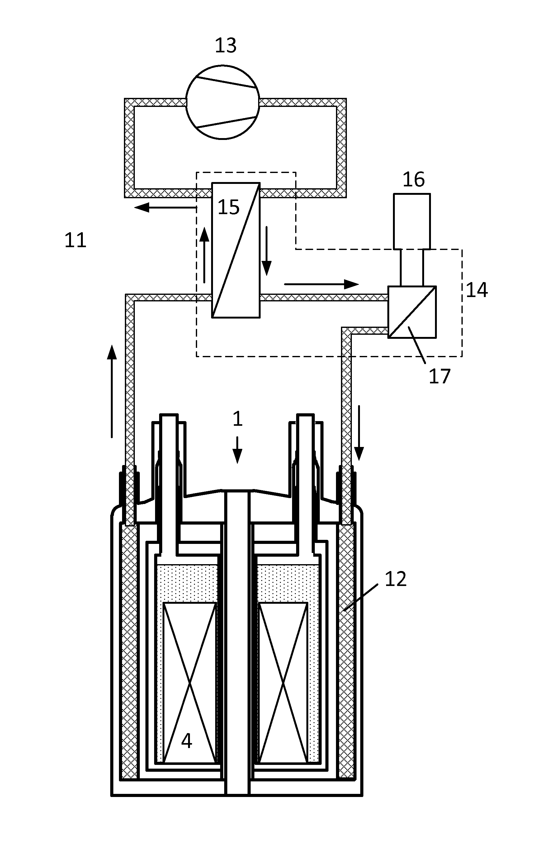
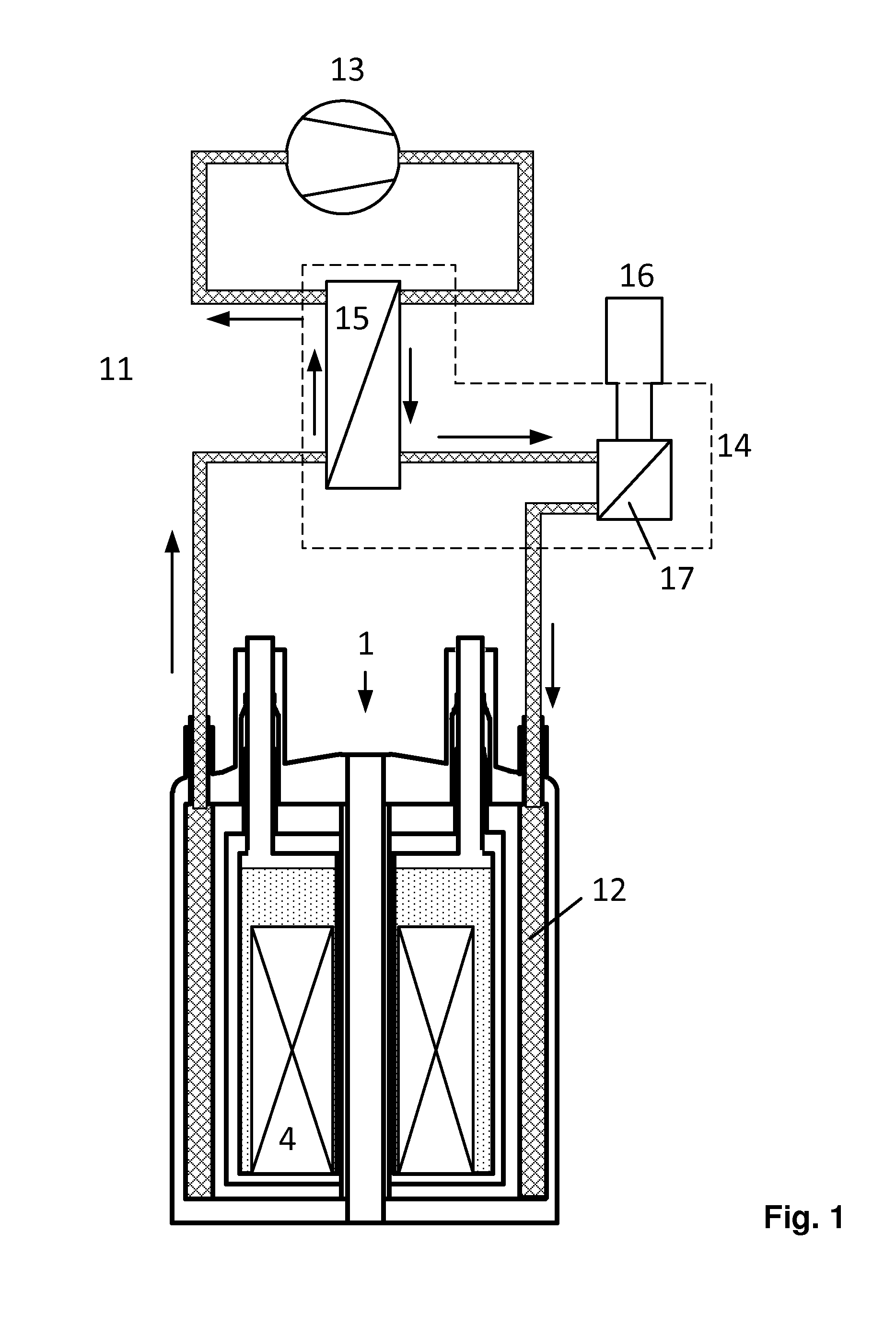
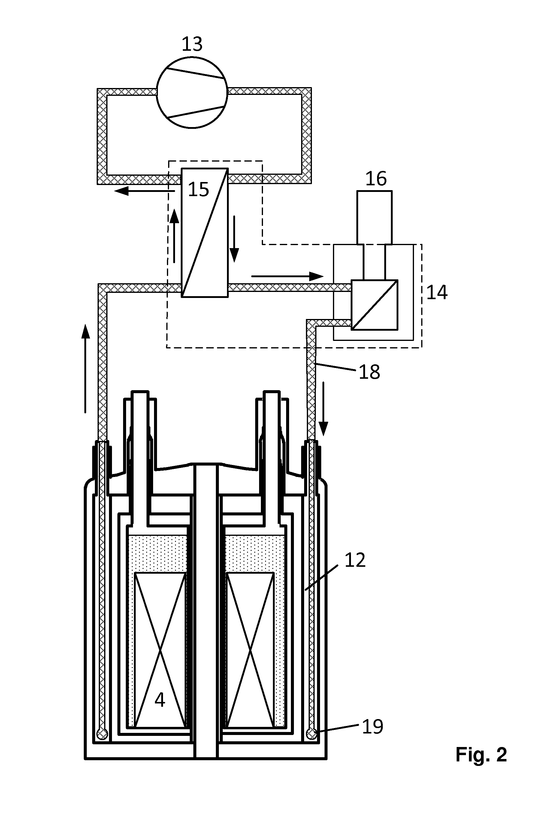
[0052]The present invention concerns, in general, a method for converting a conventional cryostat configuration of prior art, which is schematically illustrated in FIG. 8 and which has been extensively discussed above.

[0053]The cryostat configuration 1 has a room temperature vacuum container 10 housing a first container 2 with a liquid helium bath 3, the operating temperature of which is kept below 5K by means of helium evaporation, wherein the room temperature vacuum container 10 additionally contains a second container 6 which is filled with a liquid nitrogen bath 7 for thermally shielding the first container 2, and can be kept at an operating temperature of 75 to 80K by means of nitrogen evaporation.

[0054]The cryostat configuration 1 according to prior art and illustrated in FIG. 8, as well as the inventive configuration are typically used for NMR devices. The first container 2 of the configuration 1 is filled with liquid helium 3 and generally contains a superconducting magnet c...


PUM


Abstract

A method for converting a cryostat configuration (1) having a first container (2) with a liquid helium bath (3) and a second container (6) which is filled with liquid nitrogen (7) is characterized in that a cooling medium (12) which is in a gaseous state at a temperature of 60K and a pressure of 1 bar, is introduced into the second container and is cooled by a refrigerator (16) by means of a cooling circuit (11), the coolant lines of which are guided into the second container, to an operating temperature of ≦60K. With this retrofit for existing cryostat configurations that utilize both liquid helium and also liquid nitrogen for cooling a superconducting coil, use of liquid nitrogen can be completely avoided and the evaporation rate of the liquid helium can also be considerably reduced without having to re-liquefy the cryogens used.

Description

[0001]This application claims Paris convention priority from DE 10 2013 213 020.1 filed Jul. 3, 2013, the entire disclosure of which is hereby incorporated by reference.BACKGROUND OF THE INVENTION[0002]The invention concerns a method for converting a cryostat configuration comprising a room temperature vacuum container containing a first container with a liquid helium bath, the operating temperature of which is kept below 5K by means of helium evaporation, wherein the room temperature vacuum container also encloses a second container which is filled with liquid nitrogen for thermally shielding the first container and can be kept at an operating temperature of between 75 and 80K by means of nitrogen evaporation.[0003]The structure and field of use of a configuration of this type, wherein both containers are arranged inside a room temperature vacuum container, is disclosed e.g. in U.S. Pat. No. 5,267,445.[0004]A cryostat configuration of this type is used, in particular, for cooling s...

Claims


Application Information

Patent Timeline
Patent Type & Authority Applications(United States)
IPC IPC(8): F25B9/00
CPCF25B9/00F25B9/002F25D17/00F25D19/00G01R33/3815H01F6/04G01R33/3804F17C2221/014F17C2221/017F17C2270/0536
Inventor KRAUS, ANDREASSCHAUWECKER, ROBERTHINDERER, JOERG
Owner BRUKER SWITZERLAND AG
Why Eureka
Try Eureka