Low-power delay buffer circuit
a delay buffer and low-power technology, applied in the field of delay buffers, can solve the problems of mainly power consumption of sram-based delay buffers, limited capacity to sustain these devices, and high power consumption, and achieve the effect of less layout area
- Summary
- Abstract
- Description
- Claims
- Application Information
AI Technical Summary
Benefits of technology
Problems solved by technology
Method used
Image
Examples
Embodiment Construction
[0025]In the following, detailed description along with the accompanied drawings is given to better explain preferred embodiments of the present invention.
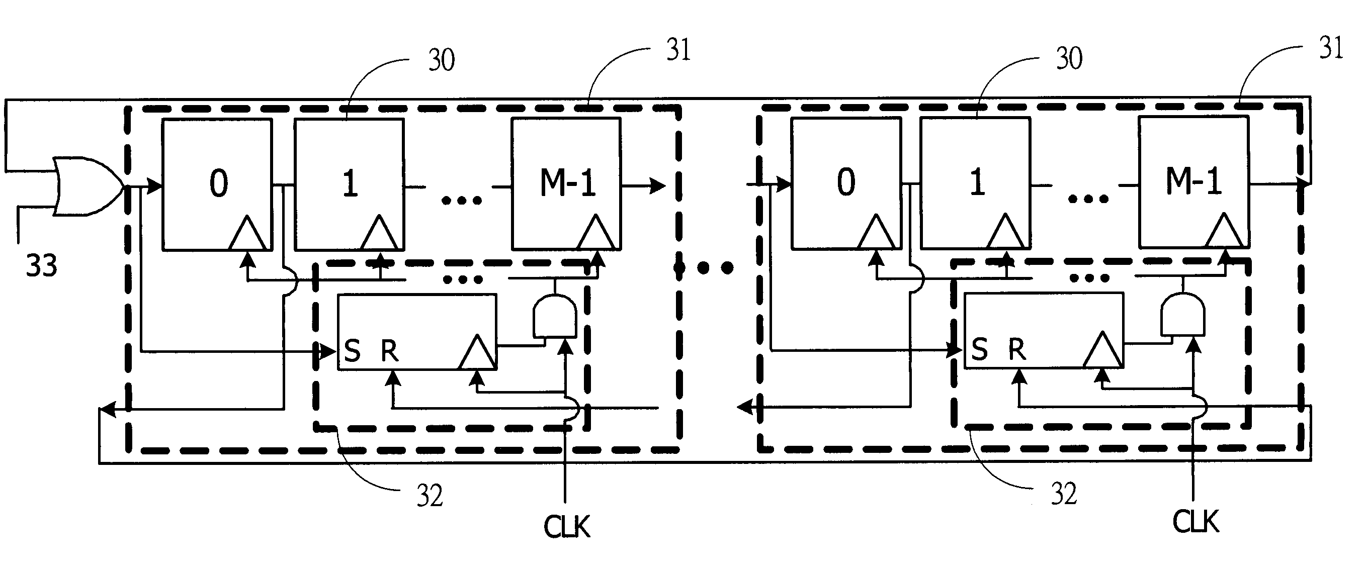
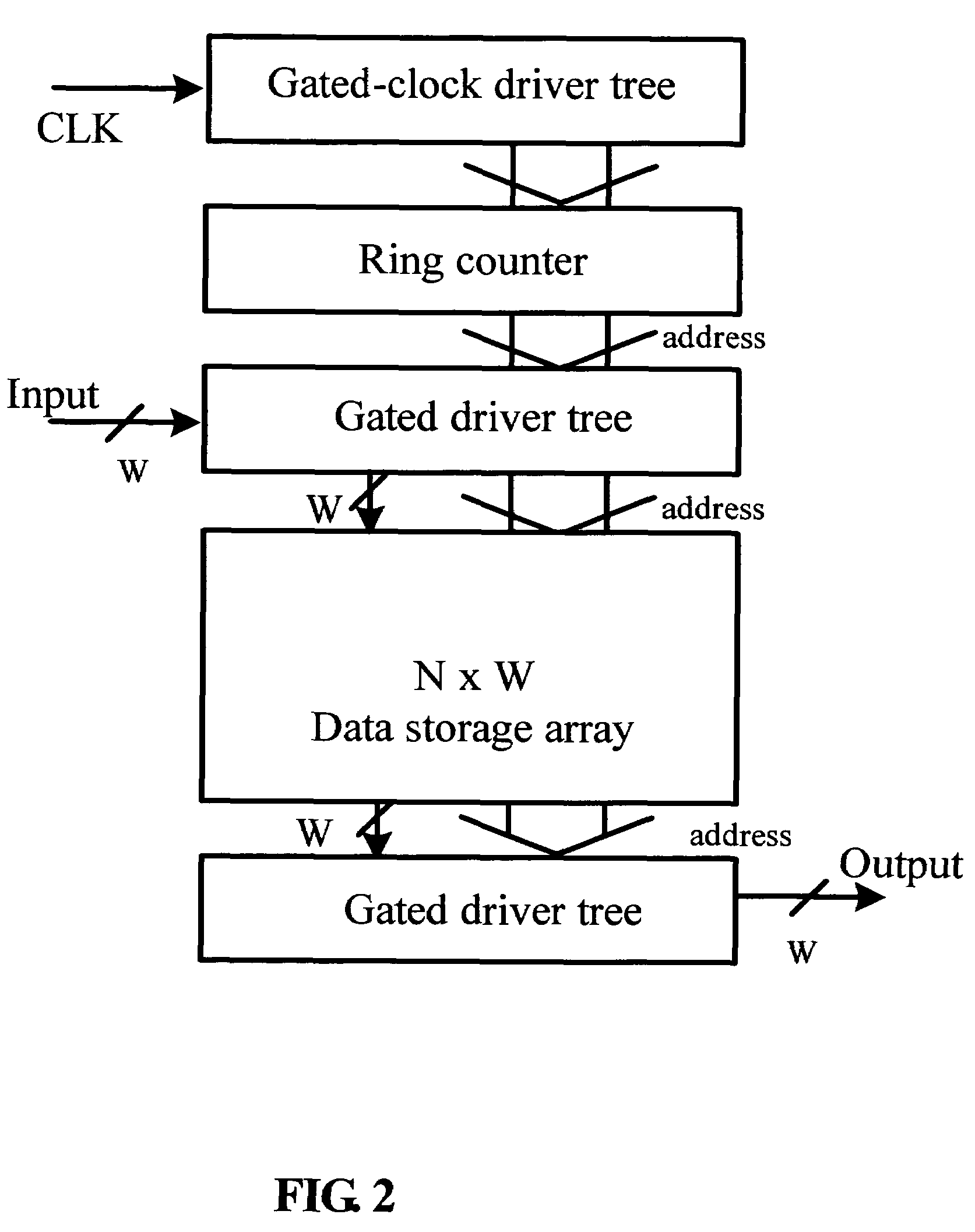
[0026]The delay buffer circuit of the present invention utilizes a ring counter as an address decoder similar to that of a SRAM memory. In addition, a latch array or similar memory is used for the storage of data. FIG. 3 is a schematic diagram showing an N×W delay buffer circuit composed of a ring counter and a latch array. As illustrated, the latch array is composed of N groups of latches 22 and each group of latches 22 contains W latches (not shown in FIG. 2), jointly for the storage a W-bit data. The input port D and output port Q of the N groups of latches 22 are connected to the input bus 21 and output bus 23, which in turn connect to two registers 24 and 25 respectively. The ring counter is composed of N series-connected shift registers 20, with the output of the last shift register 20 (numbered N−1) looped back to the input...
PUM
 Abstract
Description
Claims
Application Information
 - R&D
- Intellectual Property
- Life Sciences
- Materials
- Tech Scout
- Unparalleled Data Quality
- Higher Quality Content
- 60% Fewer Hallucinations
Browse by: Latest US Patents, China's latest patents, Technical Efficacy Thesaurus, Application Domain, Technology Topic, Popular Technical Reports.
© 2025 PatSnap. All rights reserved.Legal|Privacy policy|Modern Slavery Act Transparency Statement|Sitemap|About US| Contact US: help@patsnap.com


