Rate control method for video transcoding

a video transcoding and rate control technology, applied in the field of system and method for the compression of digital images, can solve the problems of large amount of data required to create a high-definition digital image, failure to consider image quality, and loss of all similarity

Inactive Publication Date: 2007-01-30
CISCO SYST CANADA
View PDF23 Cites 98 Cited by
  • Summary
  • Abstract
  • Description
  • Claims
  • Application Information

AI Technical Summary

Benefits of technology

[0015]The present invention relates to a system and method for rate ...

Problems solved by technology

Creating a high definition digital image requires a large amount of data.
Once the scene changes, however, some or all similarity may be lost.
Further, because it addresses only bit rate it fails to consider image quality.
By doing so, the choice of a partic...

Method used


Image

  • Rate control method for video transcoding
  • Rate control method for video transcoding
  • Rate control method for video transcoding

Examples


Embodiment Construction

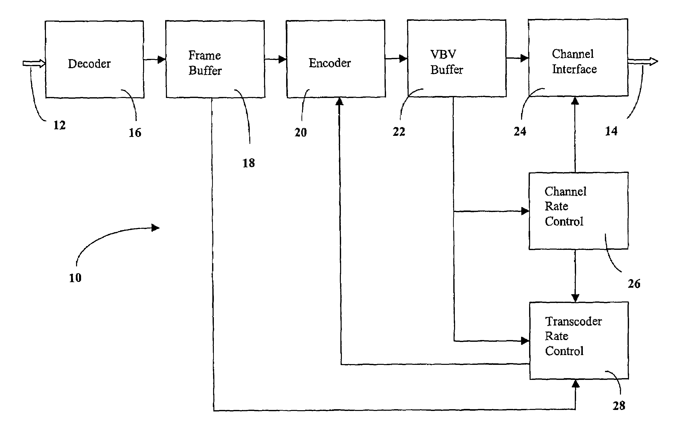
[0046]The transmission and reception of digital video signals requires complex hardware and software components. It is not the intent of this disclosure to address all such components but rather to address the specific areas within a digital video system in which the present invention may be utilized.

[0047]Referring now to FIG. 1, a block diagram of a transcoder is shown generally as 10. Source stream 12 provides the input to transcoder 10. For the purpose of simplicity the reader may think of source stream 12 as a high bit rate MPEG-2 stream from a DVD. However, it is not the intent of the inventors to restrict stream 12 to the format that is defined within the MPEG-2 standard, or to a specific source. Transcoder 10 receives source stream 12 and through a series of steps converts stream 12 to reformatted stream 14. The intent of creating reformatted stream 14 is to reduce the amount of data to be transmitted to an end user. As an example, reformatted stream 14 may be sent to a sett...


PUM


Abstract

The present invention discloses a system and method for rate control of MPEG video streams to achieve a target bit rate in a transcoder at the best visual quality possible. The invention monitors video buffer fullness for selecting the amount of rate reduction necessary to achieve a target bit rate. The invention also utilizes a method for selective requantization of DCT coefficients to assure visual quality.

Description

FIELD OF THE INVENTION[0001]The present invention relates generally to systems and methods for the compression of digital images. More specifically, the present invention relates to reducing the video bit rate of an MPEG stream to accurately produce a constant bit rate stream from an encoded video stream.BACKGROUND OF THE INVENTION[0002]Creating a high definition digital image requires a large amount of data. As stated by John Wiseman in An Introduction to MPEG Video Compression; [0003] One of the formats defined for HDTV broadcasting within the United States is 1920 pixels horizontally by 1080 lines vertically, at 30 frames per second. If these numbers are all multiplied together, along with 8 bits for each of the three primary colors, the total data rate required would be approximately 1.5 Gb / sec. Because of the 6 MHz channel bandwidth allocated, each channel will only support a data rate of 19.2 Mb / sec, which is further reduced to 18 Mb / sec by the fact that the channel must also ...

Claims


Application Information

Patent Timeline
IPC IPC(8): H04N7/12
CPCH04N19/176H04N19/61H04N19/40H04N19/152H04N19/126
Inventor COTE, GUYWINGER, LOWELLGALLANT, MICHAEL
Owner CISCO SYST CANADA
Why Eureka
Try Eureka