Method, apparatus and program storage device for providing clocks to multiple frequency domains using a single input clock of variable frequency

Inactive Publication Date: 2007-01-30
IBM CORP
View PDF18 Cites 29 Cited by
  • Summary
  • Abstract
  • Description
  • Claims
  • Application Information

AI Technical Summary

Benefits of technology

[0011]The present invention solves the above-described problems by generating independent clock signals at predetermined clock frequency targets in response to control signals that are based on a determined bus clock frequency.
[0012]A clock circuit in accordance with the principles of the present invention includes a bus clock determining circuit, the bus clock determining circuit monitoring the bus clock for providing a bus clock determination value, a controller, coupled to the bus clock determining circuit, the controller receiving the bus clock determination value and generating independent control signals based on the determined bus clock frequency and predetermined clock frequency targets and a clock signal generator, coupled to the controller, for receiving the independent control signals and generating clock signals at the predetermined clock frequency targets in response to the independent control signals.
[0013]In another embodiment of the present invention, an application specific integrated circuit is provided. The application specific integrated circuit includes a plurality of interfaces, the interfaces providing access to asynchronous devices and a clock circuit for providing clocks to multiple frequency domains for transferring data between the plurality of interfaces using a single input clock of variable frequency, the clock circuit further including a bus clock determining circuit, the bus clock determining circuit monitoring the bus clock for providing a bus clock determination value, a control

Problems solved by technology

This creates performance difficulties due to having to use methods to synchronize the data.
More importantly this creates tremendous challenges in verifying functionality before the ASIC is sent to a foundry for fabrication.
Since many of the clocks in the example above have a range of valid frequencies, verification becomes very complex.
However, using multiple oscillators has the disadvantage of multiple parts.
Further, this will be more costly and will result in worse reliability and more difficulty placin

Method used


Image

  • Method, apparatus and program storage device for providing clocks to multiple frequency domains using a single input clock of variable frequency
  • Method, apparatus and program storage device for providing clocks to multiple frequency domains using a single input clock of variable frequency
  • Method, apparatus and program storage device for providing clocks to multiple frequency domains using a single input clock of variable frequency

Examples


Embodiment Construction

[0025]In the following description of the exemplary embodiment, reference is made to the accompanying drawings which form a part hereof, and in which is shown by way of illustration the specific embodiment in which the invention may be practiced. It is to be understood that other embodiments may be utilized as structural changes may be made without departing from the scope of the present invention.

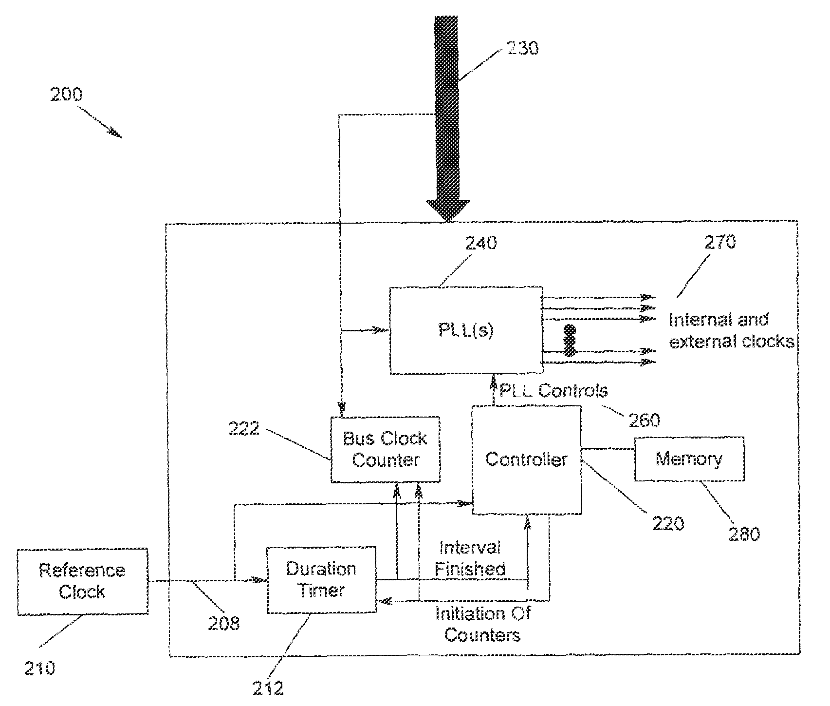
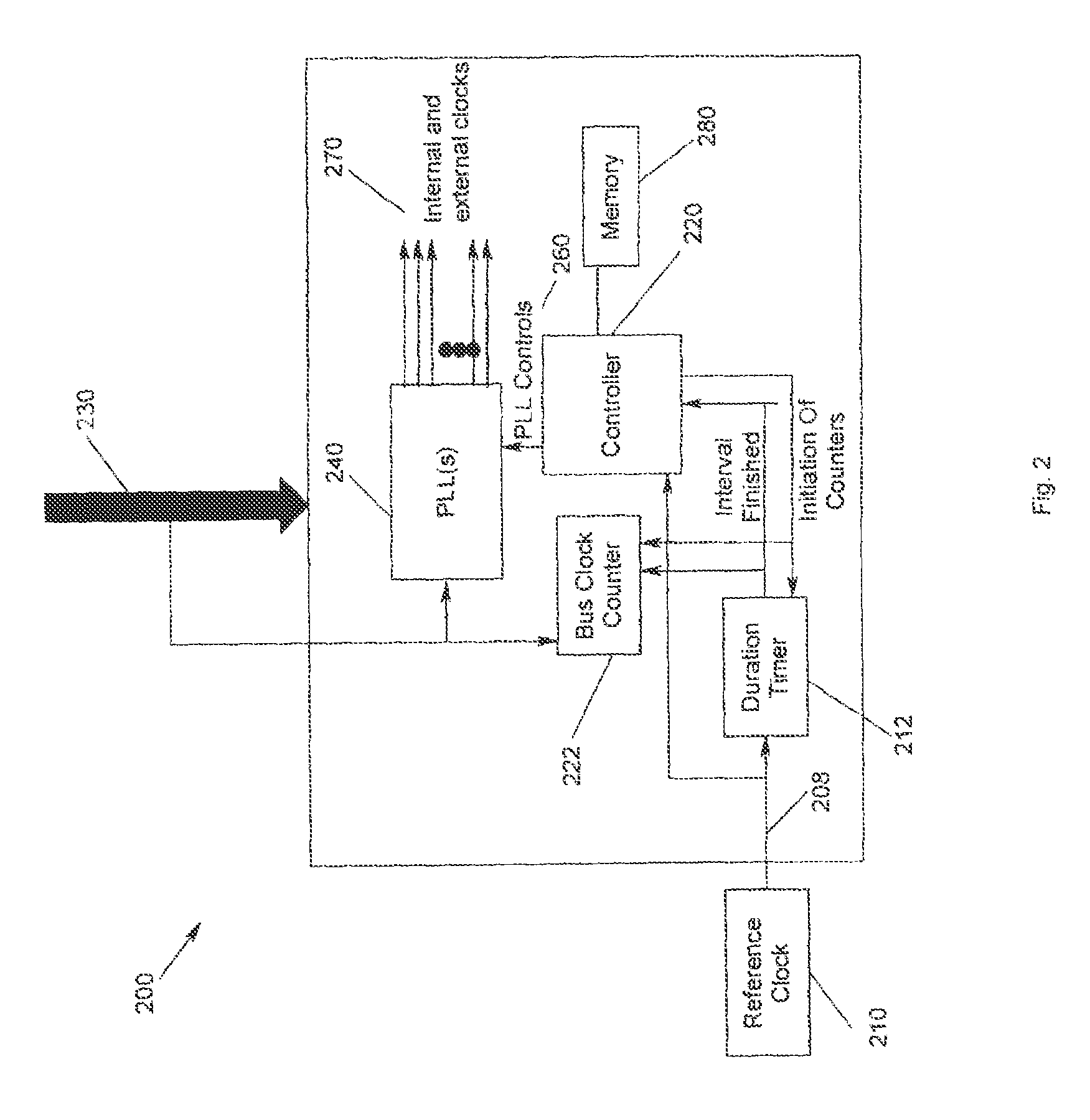
[0026]The present invention provides a method, apparatus and program storage device for providing clocks to multiple frequency domains using a single input clock for variable frequency. Independent clock signals are generated at predetermined clock frequency targets in response to control signals that are based on a determined bus clock frequency.

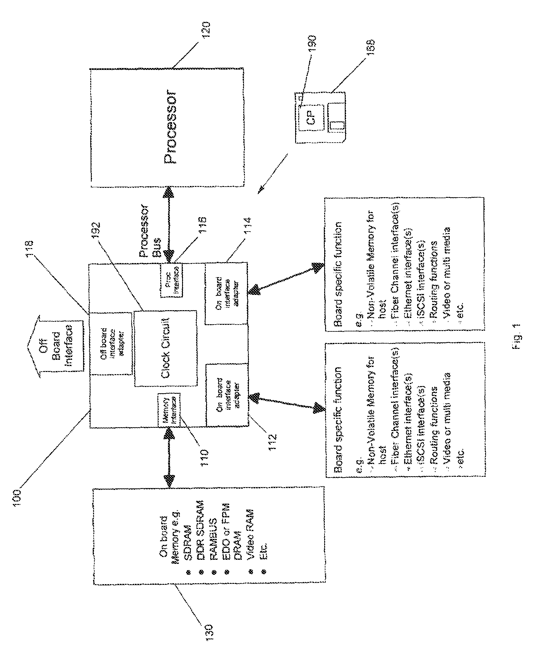
[0027]FIG 1 illustrates an ASIC 100 with multiple variable interfaces 110–118 according to the present invention. In FIG. 1, there are 5 interfaces 110–118 depicted. However, the present invention is not meant to be limited to the number or type o...


PUM


Abstract

A method, apparatus, and program storage device for providing clocks to multiple frequency domains using a single input clock of variable frequency. Independent clock signals are generated at predetermined clock frequency targets in response to control signals that are based on a determined bus clock frequency.

Description

BACKGROUND OF THE INVENTION[0001]1. Field of the Invention[0002]This invention relates in general to timing and clock systems in integrated electronics, and more particularly to a method, apparatus and program storage device for providing clocks to multiple frequency domains using a single input clock of variable frequency.[0003]2. Description of Related Art[0004]Many complex integrated circuits, and in particular application specific integrated circuits (ASICs), have multiple variable interfaces to allow for interconnecting different components. For example, an ASIC may include an off-board interface, a processor bus, standard interfaces and memory interfaces. In addition to these interfaces, an ASIC may also include one or more internal clocks which could be asynchronous to all of the interfaces.[0005]However, data may need to be transferred between the interfaces on the chip and across asynchronous boundaries. This creates performance difficulties due to having to use methods to ...

Claims


Application Information

Patent Timeline
IPC IPC(8): G06F1/06
CPCG06F1/06
Inventor MCDEVITT, HUGH W.SPANEL, CAROLWALLS, ANDREW D.
Owner IBM CORP
Why Eureka
Try Eureka