Vacuum cleaner device with a screw conveyor

a vacuum cleaner and screw conveyor technology, applied in the direction of cleaning filter means, separation processes, filtration separation, etc., can solve the problems of unsatisfactory hygienic point of view, varies the filling state of the container or the bag, and is not well suited to be used with cyclonic vacuum cleaners. , to achieve the effect of simple dust collection system

Inactive Publication Date: 2007-02-06
AB ELECTROLUX
View PDF11 Cites 33 Cited by
  • Summary
  • Abstract
  • Description
  • Claims
  • Application Information

AI Technical Summary

Benefits of technology

[0007]This invention achieves a simple dust collecting system for cyclone vacuum cleaners and creates a level sensing means for the dust in the collecting container. This is achieved by means of a device having a particle separator, which is provided with an inlet for dust lad

Problems solved by technology

However, this is not satisfactory from a hygienic point of view.
A disadvantage with these two arrangements is that the filling state of the container or the bag varies depending on the type of particles that the dust-laden air brings into the co

Method used


Image

  • Vacuum cleaner device with a screw conveyor
  • Vacuum cleaner device with a screw conveyor

Examples


Embodiment Construction

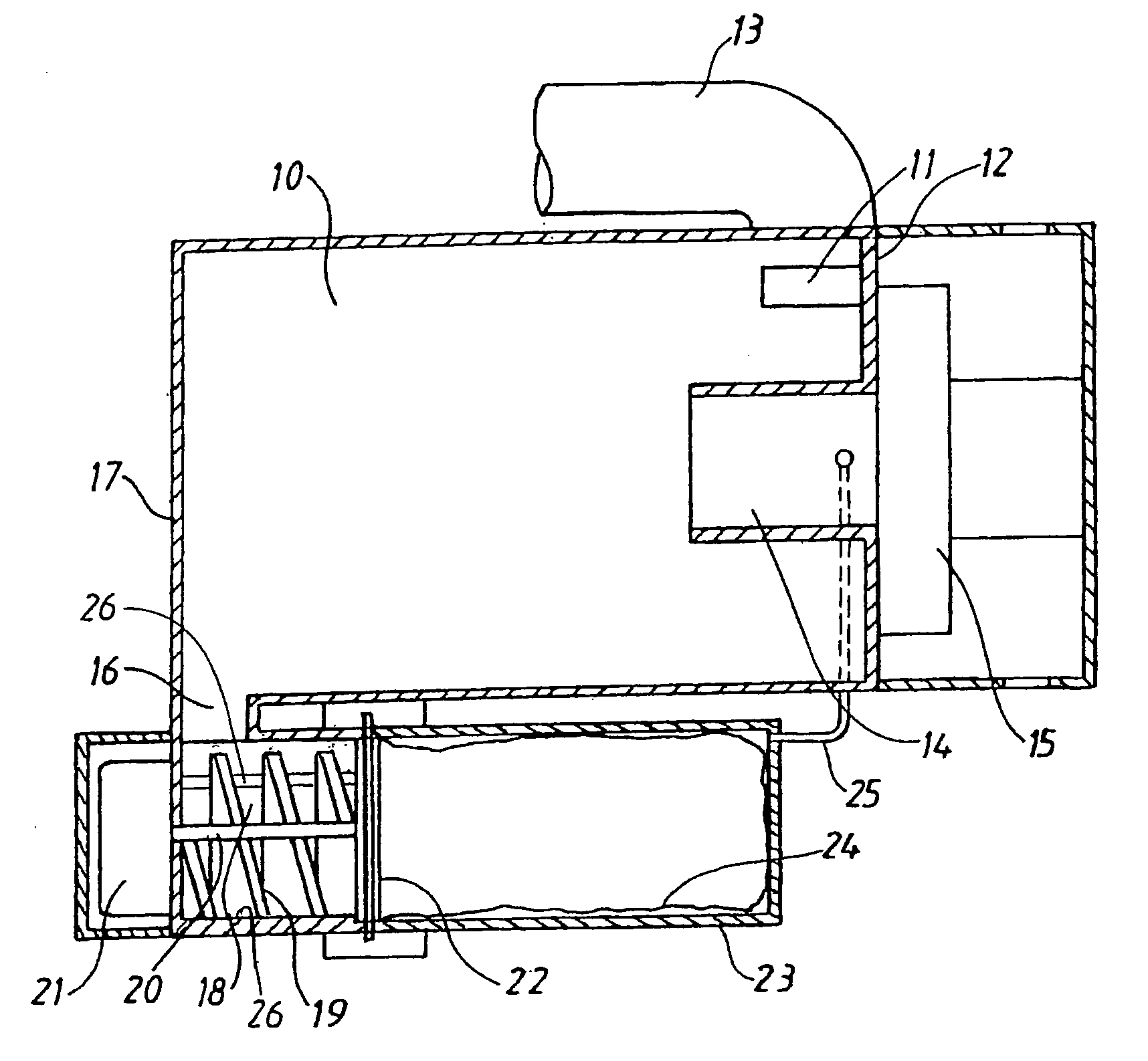
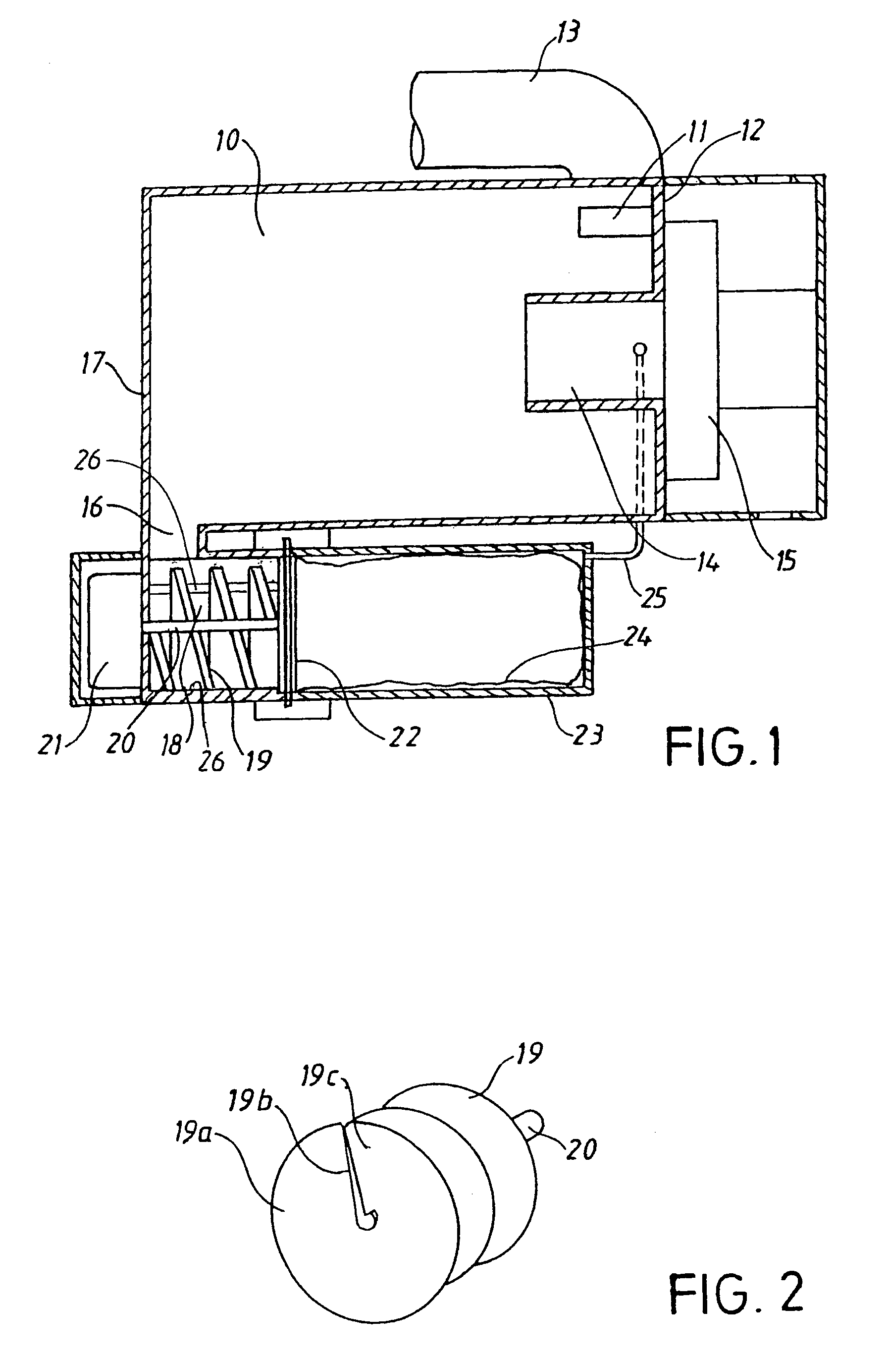
[0011]The vacuum cleaner, shown in FIG. 1, comprises a cylindrical separation chamber 10 having an inlet 11 for dust-laden air. The inlet is placed close to a first end wall 12 of the chamber 10. The inlet 11 is connected to an inlet tube 13 to which a vacuum cleaner nozzle (not shown) is connected and is designed such that air mainly flows in tangentially with respect to the chamber 10. The chamber 10 is also provided with a tube-shaped outlet 14 for cleaned air. This tube-shaped outlet 14 is coaxially to the chamber 10 and extends from said end wall 12 somewhat into the chamber. The tube-shaped outlet 14 is connected to a vacuum source, for instance, a fan unit 15 driven by an electric motor (not shown).

[0012]The chamber 10 also has a particle outlet 16 arranged close to a second end wall 17 of the separation chamber 10. The particle outlet 16 is connected to a cylindrical conveying chamber 18, which together with a screw 19 constitutes a screw conveyor or compactor for the partic...


PUM

PropertyMeasurementUnit
Pressureaaaaaaaaaa
Poweraaaaaaaaaa
Currentaaaaaaaaaa

Abstract

A device for a vacuum cleaner comprising a particle separator, which is provided with an inlet (11) for dust laden air, an outlet (16) for the separated particles, and an outlet (14) for cleaned air that is connected to a vacuum source (14). The particle outlet (16) is connected to a screw conveyor (18, 19), which is provided with an outlet part ending in a mainly closed collecting chamber (23) for the separated particles.

Description

[0001]This application claims the benefit of International Application Number PCT / SE01 / 02878, which was published in English on Jul. 18, 2002.BACKGROUND OF THE INVENTION[0002]This invention relates to a device for a vacuum cleaner with a particle separator, which is provided with an inlet for dust-laden air, an outlet for the separated particles, and an outlet for cleaned air.[0003]Vacuum cleaners that separate particles from an airflow by cyclonic action are previously known, see for instance U.S. Pat. No. 4,463,748. Such vacuum cleaners do not use traditional filter bags where dust particles are separated from the dust-laden air, but are instead provided with a container where dust particles are collected when the airflow is rotated in a cylindrical separation chamber. Due to the centrifugal forces, the particles are thrown towards the periphery of the chamber where the inlet of the container is placed. When the container has been filled, it is removed from the vacuum cleaner and ...

Claims


Application Information

Patent Timeline
IPC IPC(8): A47L9/10A47L9/16
CPCA47L9/1683A47L9/108
Inventor SJOBERG, GORANBERGLING, FREDRIK
Owner AB ELECTROLUX
Why Eureka
Try Eureka