Gas generator for air bag

a gas generator and air bag technology, applied in the direction of pedestrian/occupant safety arrangement, separation process, vehicular safety arrangement, etc., can solve the problems of airbags not being inflated and developed in sufficient quantities, adverse possibility, and gas generating agent used for gas generators not always high ignitability

Active Publication Date: 2007-02-06
DAICEL CHEM IND LTD
View PDF30 Cites 9 Cited by
  • Summary
  • Abstract
  • Description
  • Claims
  • Application Information

AI Technical Summary

Benefits of technology

[0038]The position of the communication hole may be determined based on the center of the communication hole. Since the communication hole has a small diameter (e.g., 1 to 4 mm), even if the position is determined based on the center of the hole, the effect of the invention is not deteriorated. When a plurality of communication holes are arranged in the axial direction, the communication hole which is the closest to the housing bottom surface is the reference.
[0039]The position of the vent hole may be determined based on the lower end of the vent hole and may be at a position where the communication hole and the vent hole are not exactly opposite to each other (communication hole is exactly opposite to a portion of the plate where no vent hole is formed).
[0040]This invention provides the means for more reliably exhibiting the effect of the invention according to the fifth aspect of the invention, and the adjusting ranges of the forming position of the communication hole and the position of the tip end of the inner cylindrical shielding plate (when there exists the vent hole, the position of the vent hole) are determined.
[0041]The positional relationship can appropriately be adjusted such that the respective elements are in the above ranges, and the communication hole and the inner cylindrical shielding plate are exactly opposite to each other. For example, when the forming position of the communication hole is 0.05 L, the position of the tip end of the shielding plate can be 0.3 L, and when the forming position of the vent hole is 0.6 L, the position of the tip end of the shielding plate can be 0.8 L.
[0042]As to the seventh aspect of the invention, in the gas generator for an air bag of the invention according to the fifth aspect of the invention, when the lower end opening peripheral edge of the inner cylindrical shielding plate comes into contact with the housing bottom surface and a space is generated between the housing ceiling surface and the upper end opening peripheral edge of the inner cylindrical shielding plate, or when the lower end opening peripheral edge of the inner cylindrical shielding plate comes into contact with the housing bottom surface and the upper end opening peripheral edge of the inner cylindrical shielding plate comes into contact with the housing ceiling surface and a plurality of vent holes are formed in the upper end opening peripheral edge,
[0043]a relationship between a forming position of the communication hole, which is formed in the peripheral wall of the inner cylinder, in the axial direction of the housing and a position of the tip end of the inner cylindrical shielding plate or the forming position of the vent hole may be set such that if a height from the housing bottom surface to the housing ceiling surface is defined as L,

Problems solved by technology

Further, a gas generating agent used for the gas generator does not always have high ignitability depending upon its composition.
In such a case, there is an adverse possibility that the air bag cannot sufficiently be inflated and developed.

Method used


Image

  • Gas generator for air bag
  • Gas generator for air bag
  • Gas generator for air bag

Examples


first embodiment

(1) First Embodiment

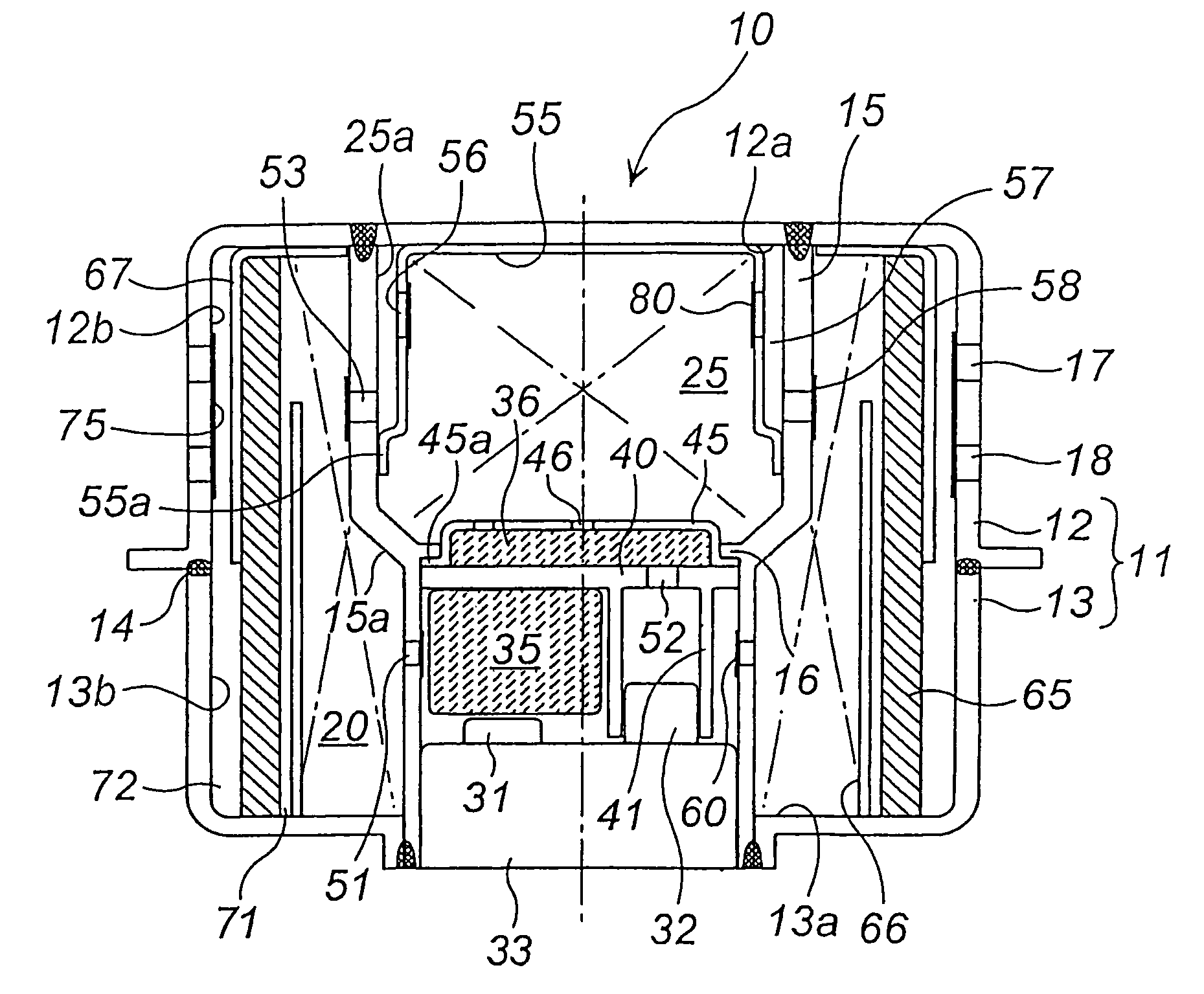
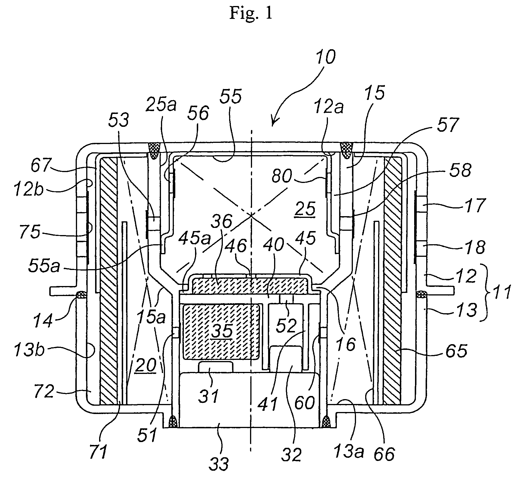
[0073]Embodiments of the present invention will be explained with reference to the drawings. FIG. 1 is an axial sectional view of a gas generator for an air bag according to the first embodiment of the present invention. In the following description, a vertical relationship such as “upper” or “lower” is indicated with reference to FIG. 1, “the axial direction” means the axial direction of a housing, and “the radial direction” means the radial direction of the housing.

[0074]In a gas generator 10, an outer shell container is formed of a housing 11. The housing 11 is formed by bonding a diffuser shell 12 to a closure shell 13. The diffuser shell 12 and the closure shell 13 form an inner accommodating space. The diffuser shell 12 and the closure shell 13 are welded to each other through welded portion 14. In FIG. 1, other shaded portions also indicate welded portions.

[0075]The diffuser shell 12 is provided with a necessary number of gas discharge ports 17 and 18. Dia...

second embodiment

(2) Second Embodiment

[0121]Another embodiment of the present invention will be explained with reference to the drawings. FIG. 5 is an axial sectional view of the gas generator for an air bag. FIG. 6 is a view for explaining a positional relationship of constituent elements shown in FIG. 5. In the following description, “the axial direction” means the axial direction of a housing, and “the radial direction” means the radial direction of the housing.

[0122]The gas generator 100 for an air bag is formed with an outer shell container formed of a housing 101. The housing 101 is formed by joining a diffuser shell 102 and a closure shell 103 with each other. The diffuser shell 102 and the closure shell 103 form an inner accommodating space. The diffuser shell 102 and the closure shell 103 are welded at a welding portion 104.

[0123]The diffuser shell 102 is provided with a necessary number of gas discharge ports 107, 108 and 109, and the ports are closed with aluminum seal tapes 110 for preve...


PUM

PropertyMeasurementUnit
thicknessaaaaaaaaaa
bulk densityaaaaaaaaaa
combustion temperatureaaaaaaaaaa

Abstract

A gas generator for an air bag includes a filter having excellent cooling effect. A gas flow as illustrated in the drawings is formed by effect of the inner cylindrical shielding plate 66, the outer cylindrical shielding plate 67, the first gap 71 and the second gap 72, which sandwich a cylindrical filter 65 for cooling a combustion gas from the both side. Thus, the cooling effect of the combustion gas is enhanced.

Description

CROSS-REFERENCE TO RELATED APPLICATIONS[0001]This Nonprovisional application claims priority under 35 U.S.C. § 119(e) on U.S. Provisional Application Nos. 60 / 432,663 and 60 / 520,244 filed on Dec. 12, 2002 and Nov. 17, 2003 and under 35 U.S.C. § 119(a) on Patent Application Nos. 2002-356704 and 2003-382436 filed in Japan on Dec. 9, 2002 and Nov. 12, 2003, the entire contents of which are hereby incorporated by reference.BACKGROUND OF THE INVENTION[0002]1. Field of the Invention[0003]The present invention relates to a gas generator for an air bag for protecting a passenger from an impact.[0004]2. Description of Related Art[0005]A gas generator for an air bag incorporated in an air bag system mounted in an automobile needs to satisfy various requirements in view of protection of a passenger. For example, the gas generator is required to reliably operate even after ten years which correspond to normal service life of a vehicle mounted with the gas generator. Further, when the air bag is ...

Claims


Application Information

Patent Timeline
Patent Type & Authority Patents(United States)
IPC IPC(8): B60R21/26B01D46/24B60R21/264
CPCB01D46/2403B60R21/2644B01D2279/10B60R2021/2648B60R2021/2633
Inventor MATSUDA, NAOKIYAMAZAKI, MASAYUKIIWAI, YASUNORI
Owner DAICEL CHEM IND LTD
Why Eureka
Try Eureka