Adjustable sifting shovel

a shovel and adjustment technology, applied in the field of shovels, can solve the problems of large number of such minor bits of debris, large number of such small bits of debris, and large number of similar problems,

Inactive Publication Date: 2007-02-06
GORBET CHARLES ELTON
View PDF6 Cites 7 Cited by
  • Summary
  • Abstract
  • Description
  • Claims
  • Application Information

AI Technical Summary

Benefits of technology

[0009]The present invention teaches a shovel having a scoop with a bottom perforated by apertures and a movable sifting plate held in one of a plurality of possible positions by means of a retainer plate. The sifting plate may have apertures which do not overlap the apertures of the scoop in a first position, thus keeping the bottom of the shovel scoop closed for use as a shovel. In a second position, the sifting plate apertures may overlap the apertures of the scoop bottom so as to provide a degree of sifting ability. Either set of apertures may have a screen thereacross.
[0010]The retaining plate may be biased by a spring so as to hold the sifting plate in position. The retaining plate spring may sit on a post projecting from the retaining plate, under pressure from an arm projecting from the scoop. A tab, pin, or other projection from the retaining plate may pass through the sifting plate at a positioning slot and into a retaining slot in the scoop, thereby preventing motion of the sifting plate unless the retaining plate is moved, against the urging of the spring, into a position at which the tab does not project through the positioning slot into the retaining slot.

Problems solved by technology

One problem encountered during shoveling is that it may be necessary to pick up a discrete object from a surface composed of smaller particulate matter.
After a windstorm, a large number of such minor bits of debris may be present.
However, when attempting to shovel up such items, the user inevitably is left with a large quantity of the sand which is scooped up into the shovel scoop with the pebble or leaf.
A number of similar problems occur.
Picking up larger items from a bed of leaves, gravel or moss may pose similar problems.
However, such devices have a substantial disadvantage in that they are not useful for moving the filtered particles if that is needed, cannot be used to shovel and so on.

Method used


Image

  • Adjustable sifting shovel
  • Adjustable sifting shovel
  • Adjustable sifting shovel

Examples


second embodiment

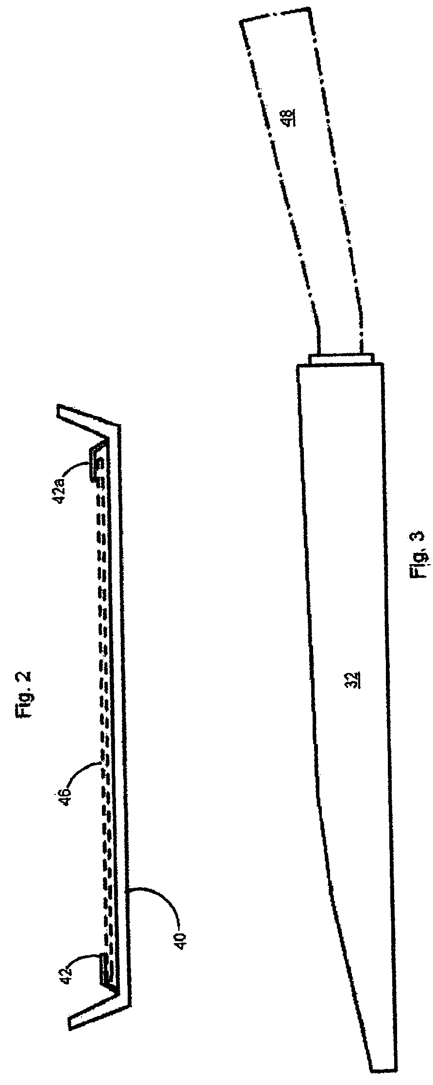
[0082]FIG. 3 is a side view of the invention in which the retaining slots do not pass entirely through the sides of the scoop and the retainer plate sits entirely within the interior of the scoop, invisible from the side. Side 32 thus hides the retainer plate.

[0083]Scoop handle 48 may be a one hand handle for a short scoop such as may advantageously be used for pet litter boxes, or may be longer for gardening work, or may be extensible, removable, etc.

[0084]FIG. 4 is a planform view of a third sifting plate embodiment of the invention. Sifting plate upper portion 50 may have projecting therefrom extension 52 which has thereon positioning slots 54a, b, c, d.

[0085]Tab 24 (FIG. 1) may pass through one selected positioning slot 54a when the sifting plate 46 is in a first position, and may pass through a different selected positioning slot 54b when the sifting plate 46 is in a second position, through a third positioning slot 54c in a third position, and so on.

[0086]Sifting openings 56 ...

fourth embodiment

[0087]FIG. 5 is a side view of a scoop of the invention in which there are multiple retaining slots to allow positioning of the retaining plate. Thus in this embodiment, there are multiple slots through the scoop 12 sides (32, 34) in order to allow a plurality of different positions of the sliding sifting plate 46. FIG. 6 is a planform view of a fifth scoop bottom according to the invention. Sifting openings 66 and blocked areas 68 may be the same width as the sifting openings 56 and blocked areas 58 of the sliding sifting plate 46, or they may be different widths, or even different lengths.

[0088]Retaining slots 60a, b, c, d pass entirely through the side 32 and allow multiple sift plate positions even in alternative embodiments in which there is only one positioning slot 54a on the sliding sift plate. However, in the best mode now contemplated, there may be multiple slots on both scoop and plate, so that a wide variety of different positions may be attained.

[0089]As an example, con...


PUM


Abstract

The present invention teaches a shovel having a scoop with a bottom perforated by apertures and a movable sifting plate held in one of a plurality of possible positions by means of a retainer plate. The sifting plate may have apertures which do not overlap the apertures of the scoop in a first position, thus keeping the bottom of the shovel scoop closed for use as a shovel. In a second position, the sifting plate apertures may overlap the apertures of the scoop bottom so as to provide a degree of sifting ability. Either set of apertures may have a screen thereacross. The retaining plate may be biased by a spring so as to hold the sifting plate in position.

Description

CROSS-REFERENCE TO RELATED APPLICATIONS[0001]This application claims the priority and benefit of U.S. Provisional Application No. 60 / 584,973 filed Jul. 1, 2004 in the name of the same inventor, Charles E. Gorbet, and entitled SHIVEL, the disclosure of which is incorporated herein by this reference thereto.FIELD OF THE INVENTION[0002]This invention relates generally to shovels and specifically to adjustable shovels.Statement Regarding Federally Funded Research[0003]This invention was not made under contract with an agency of the US Government, nor by any agency of the US Government.BACKGROUND OF THE INVENTION[0004]One problem encountered during shoveling is that it may be necessary to pick up a discrete object from a surface composed of smaller particulate matter. For example, when leveling sand for a layer of “pavers” (blocks of masonry used to construct a stone surface), a shovel user may notice a pebble or leaf that has blown onto the sand. After a windstorm, a large number of suc...

Claims


Application Information

Patent Timeline
Patent Type & Authority Patents(United States)
IPC IPC(8): B07B1/49
CPCA01B1/022E02F3/02B07B1/02
Inventor GORBET, CHARLES ELTON
Owner GORBET CHARLES ELTON
Why Eureka
Try Eureka