Internally illuminated light panel with LED modules having light redirecting devices

a technology of led modules and light panels, applied in the field of illuminated signs, can solve the problems of patchy dark regions, insufficient mixing or homogenizing at the face panel, and inability to build thin light panels or object bodies

Inactive Publication Date: 2007-02-06
LEOTEK ELECTRONICS
View PDF6 Cites 71 Cited by
  • Summary
  • Abstract
  • Description
  • Claims
  • Application Information

AI Technical Summary

Problems solved by technology

Therefore, the light panel or object body cannot be built as thin as one may desire.
For thin panel applications, there simply is insufficient mixing or homogenizing at the face panel because the light coming directly from the back of the panel is either transmitted through or reflected back at the face panel.
However, patches of dark regions can result when the to be illuminated areas are located over long distances from the light sources.
These dark regions can occur in oversized light panels or objects because the center portions of the panel are too far from the panel / object edges, and light intensity decreases significantly as the light travels over extended distances.
In addition, panels / objects with complex shapes can be difficult to illuminate evenly from irregularly shaped panel / object edges.

Method used


Image

  • Internally illuminated light panel with LED modules having light redirecting devices
  • Internally illuminated light panel with LED modules having light redirecting devices
  • Internally illuminated light panel with LED modules having light redirecting devices

Examples


Embodiment Construction

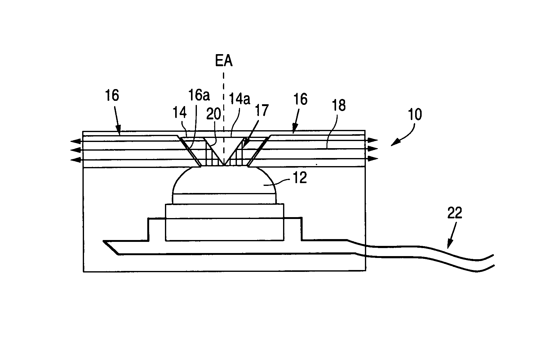
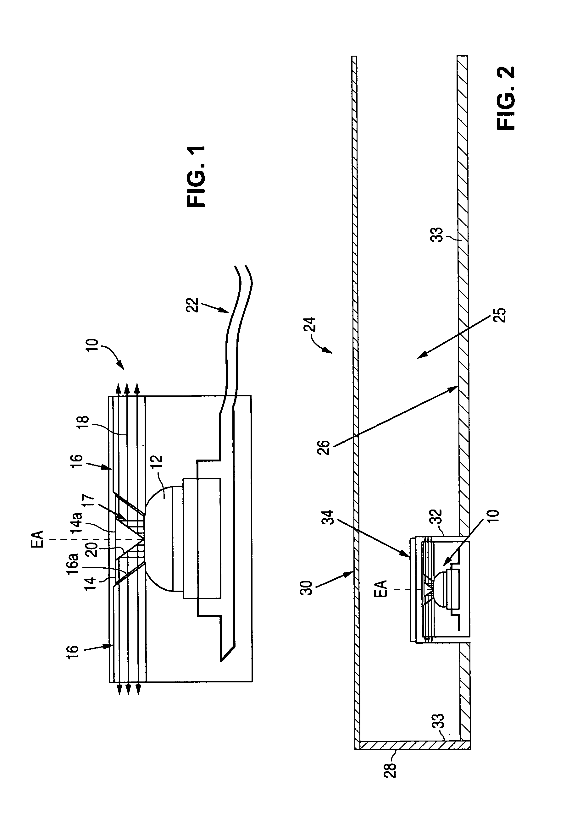
[0018]A light-emitting diode side emitting module 10 of the present invention is shown in FIG. 1. The module includes a point light source such as a light emitting diode (LED) 12 (which can include a single diode or a plurality of diodes), a light-redirecting optical device 14, and light guide element 16. The LED 12 produces an optical output generally centered around an emission axis EA and having an emission pattern that can vary widely based upon the LED model and manufacturer. Some LEDs emit most of their light in a relatively small cone of viewing angles very close to the emission axis EA. Other LEDs have a wider emission pattern with a larger cone of viewing angles. Still other LEDs emit most of the light out the sides of the LED emission housing. However, virtually all LEDs produce at least some light 17 generally parallel to the emission axis EA. The light-redirecting optical device 14 of the present invention redirects this light 17 from the LED into generally transversely ...


PUM


Abstract

An illuminated sign having front, back and side surfaces. A plurality of first cavities are formed into the back surface of the sign. A plurality of light emitting modules are disposed in the plurality of first cavities. The modules each include a light emitting diode having an emission axis and for producing at least some light output generally parallel to the emission axis, an optical device disposed adjacent the light source having a reflective surface for reflecting the light output in directions that are generally perpendicular to the emission axis, and a guide element disposed adjacent the optical device for coupling the reflected light output into the interior of the sign. The guide element includes a second cavity formed therein in which the optical device is disposed. The front surface is illuminated by the coupled light output from the light emitting modules by reflection and / or diffusion inside the sign.

Description

[0001]This application claims the benefit of U.S. Provisional Application No. 60 / 534,591, filed Jan. 5, 2004.FIELD OF THE INVENTION[0002]The present invention relates to illuminated signs, and more particularly to Light-Emitting Diode (LED) modules for various commercial signs, light panels / objects and street name signs. The new LED design improves illumination intensity and uniformity, as compared to existing technologies such as back-lit and edge-lit signs.BACKGROUND OF THE INVENTION[0003]Conventional techniques to illuminate street signs, light panels or other objects with Light-Emitting Diodes (LEDs) include placing the LED light sources at the back of the panel or object (i.e. “back-lit” type) with the light shining normally to the viewing surface (see for example U.S. Pat. Nos. 6,558,021 and 6,761,471). Back-lit light sources can be placed over a large area to illuminate a light panel or object with various shapes and sizes. As each individual light source can be placed wherev...

Claims


Application Information

Patent Timeline
Patent Type & Authority Patents(United States)
IPC IPC(8): B64D47/06F21V7/04F21V8/00F21W131/00G02B6/00G02B6/42G09F13/04
CPCG02B6/0021G09F13/0404G09F13/04G02B6/0028G02B6/0018G02B6/4214
Inventor WU, CHEN-HOHWANG, CHINMAU JAMESTU, CHIN-WANGCHUNG, CHING YUAN
Owner LEOTEK ELECTRONICS
Why Eureka
Try Eureka