
Molding insert for molding machines

a molding machine and insert technology, applied in the direction of dough shaping, shaping press rams, baking, etc., can solve the problem that the inner weight of the molded body is not sufficient to de-mold the material of the molded body

Inactive Publication Date: 2007-02-06
KOBRA FORMEN
View PDF7 Cites 13 Cited by
  • Summary
  • Abstract
  • Description
  • Claims
  • Application Information

AI Technical Summary

Benefits of technology

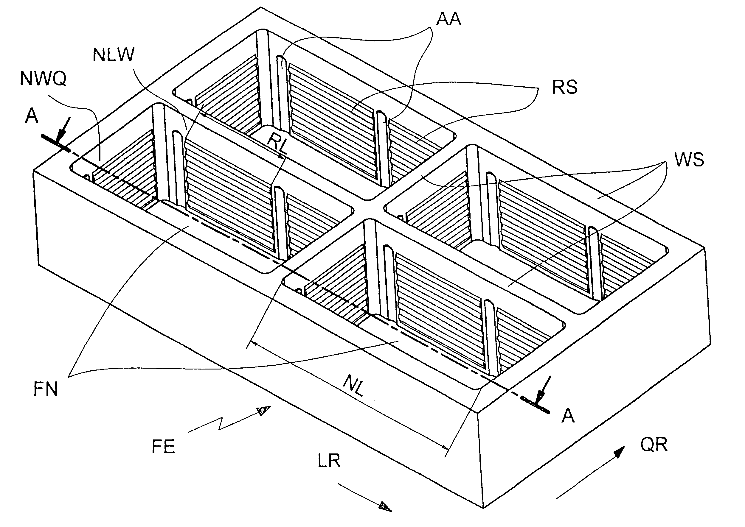
[0012]The relief has holding flanks that are inclined downward at a slant towards the interior of the mold cavity, as support surfaces on which projections of the lateral surfaces of the compacted molded body support themselves. The angle of these holding flanks from the vertical is preferably at most 30°, so that during the forced de-molding, sliding of the projections along the holding flanks takes place, with a gradual lateral deformation of the material of the molded body, preferably within the range of elastic deformation. A slight remaining deformation of the projections on the lateral surfaces is not critical, since the function of these projections, that of holding the molded body in the molding insert counter to its weight force, is eliminated after de-molding.
[0013]The inherent weight of the molded body depends not only on the volume but also on the density of the material, but this typically does not vary significantly, so that the weight of the compacted molded body can essentially be considered to be known. In the estimate of the required holding force, it must also be taken into consideration that in the case of multi-layer production, after compaction of the molding insert, movement of the compacted molded bodies takes place vertically and possibly also horizontally, and that in this connection, acceleration forces occur, which are not yet allowed to result in the molded bodies falling out of the molding insert. With regard to the deformability of the damp molded body after compaction, greater variations can occur, depending on the degree of compaction, and this can have an effect on the holding force and the maximal elastic deformability. It is therefore advantageous that the depth of the relief structure can be designed for great rigidity with low elastic deformability, and the entire holding surface of all holding flanks can be designed for low rigidity, with easy deformability of the compacted, damp molded body, within the scope of the variations to be expected.
[0014]A depth of maximally 1.5 mm, particularly of maximally 0.8 mm, proves to be advantageous for the relief depth of the relief structure. The minimal depth is advantageously 0.2 mm. In order to obtain a sufficient holding force over the sum of the holding surfaces of all the holding flanks, the cumulative expanse of all the holding flanks in the horizontal direction, parallel to the walls, is at least equal to the circumference of the molded body, preferably at least equal to twice this circumference. It is advantageous that the relief structure can have several holding flanks, one after the other, in the vertical direction, which are separated by segments of the relief structure that do not apply any holding forces.

Problems solved by technology

The relief is coordinated with the volume of the mold cavity and the material of the molded body, in such a manner that on the one hand, the inherent weight of the molded body is not sufficient to de-mold the material of the molded body from the mold cavity and, on the other hand, the molded body can be de-molded from the mold cavity, under the influence of the pressure device, without shearing off the projections that are located in depressions of the relief, on lateral surfaces of the molded body.

Method used


Image

  • Molding insert for molding machines
  • Molding insert for molding machines
  • Molding insert for molding machines

Examples


Embodiment Construction

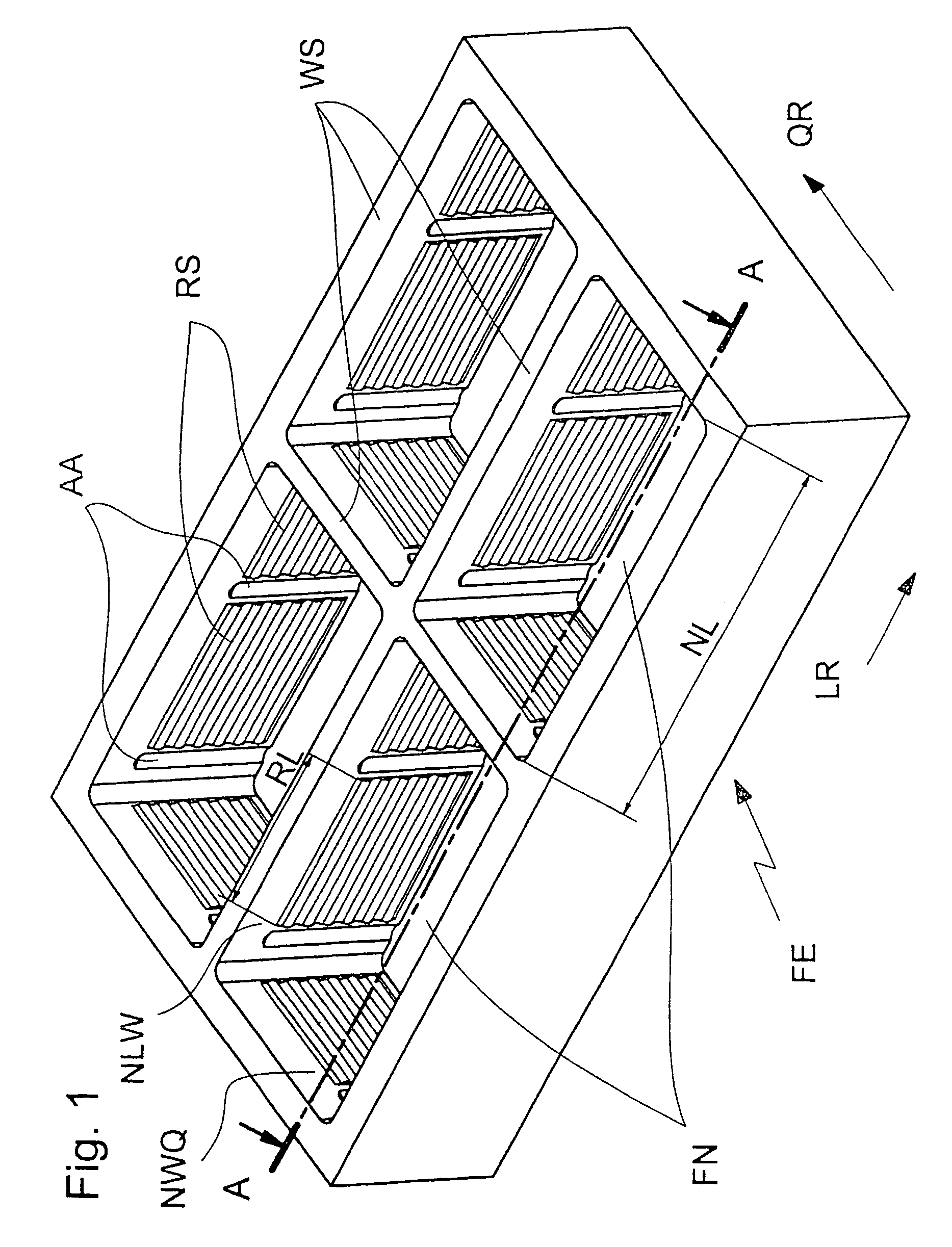
[0026]A molding insert or a detail of such a molding insert FE, having several mold cavities FN, is shown in FIG. 1, with the viewing direction being from above, at a slant, into the mold cavities. The mold cavities are approximately rectangular in the example shown, and are delimited by lateral walls or partitions WS. The mold cavities are open towards the top, so that non-compacted concrete mass can be filled into them, and pressure plates of a pressure device, which end closely with the outline of the mold cavities, can be set into them, and then pressed down by a weight or pressed downward into the mold cavities in some other manner. In operation, the molding insert is set onto a vibrating table, if necessary with the interposition of an intermediate plate, and pressed downward by means of a mold frame that is not shown in the drawing. The vibrating table is excited to produce shaking vibrations by means of shock vibration or unbalance vibration, which vibrations are transferred...


PUM

PropertyMeasurementUnit
relief depthaaaaaaaaaa
depthaaaaaaaaaa

Abstract

The invention relates to the production of multi-layered concrete moulded bodies in a moulding machine comprising a moulding insert having a plurality of mould cavities. Relief structures are arranged in the lateral walls of the mould cavities and are dimensioned in such a way that projections formed on the moulded body when the filled concrete material is compacted engage in the relief structures, thereby creating sufficient retaining force for compensating the net weight of the moulded body and enabling the moulded bodied to be extracted from the mould cavities as a result of additional demoulding forces and causing elastic deformation of the projections without any material being cut off from the projections.

Description

CROSS REFERENCE TO RELATED APPLICATIONS[0001]Applicants claim priority under 35 U.S.C. §119 of German Application No. 102 41 238.3 filed on Sep. 6, 2002. Applicants also claim priority under 35 U.S.C. §365 of PCT / EP2003 / 009652 filed on Aug. 30, 2003. The international application under PCT article 21(2) was not published in English.BACKGROUND OF THE INVENTION[0002]1. Field of the Invention[0003]The invention relates to a molding insert for molding machines, for the production of compacted molded bodies.[0004]2. The Prior Art[0005]Such molding inserts are particularly in use devices for the production of stones molded from concrete and, in this connection, form a vibrating mold, together with a mold frame. The mold cavities of a mold insert set onto a vibrating table are filled with concrete mass and closed off at the top with pressure dies. By means of vibration excitation of the vibrating table, the concrete mass is compacted to such a great extent that the damp molded stones subse...

Claims


Application Information

Patent Timeline
Patent Type & Authority Patents(United States)
IPC IPC(8): B28B7/10B28BB28B1/00B28B3/00B28B3/06B28B7/00B28B21/00E01C5/06G09F7/16
CPCB28B7/10B28B7/0064B28B3/06
Inventor BRAUNGARDT, RUDOLFSCHMUCKER, ERWIN
Owner KOBRA FORMEN
Learn More