Conductive roller

a technology of conductive rollers and conductive rollers, which is applied in the direction of shafts and bearings, corona discharge, instruments, etc., can solve the problems of liable toner dispersion, achieve high-quality images, prevent toner dispersion, and improve the electrical characteristics of conductive rollers

Inactive Publication Date: 2007-02-06
SUMITOMO RUBBER IND LTD
View PDF10 Cites 9 Cited by
  • Summary
  • Abstract
  • Description
  • Claims
  • Application Information

AI Technical Summary

Benefits of technology

[0045]As apparent from the foregoing description, according to the present invention, since the electric resistance of the conductive roller is set low and its electrostatic capacity at the frequency of 100 Hz is specified in the above-described range, the conductive roller can be reliably prevented from causing the toner dispersion. Thus it is possible to improve the electrical characteristics of the conductive roller and obtain a high-quality image.
[0046]Since the conductive elastic layer of the conductive roller of the present invention contains the rubber component selected from among the EPDM, the NBR, and the BR, the conductive elastic layer is resistant to ozone. Since the conductive elastic layer does not contain the halogen component, the halogen component does not make a secondary reaction. Further it is possible to realize reduction of the compression permanent set and the electric resistance value of the conductive roller. Thus in burning the conductive roller to discard it, there is no fear that harmful gases such as hydrogen chloride are generated. Therefore the conductive roller of the present invention does not pollute environment.
[0047]Further it is possible to provide the conductive elast

Problems solved by technology

When the polarization speed is low, th

Method used


Image

  • Conductive roller
  • Conductive roller
  • Conductive roller

Examples


examples 1 through 16

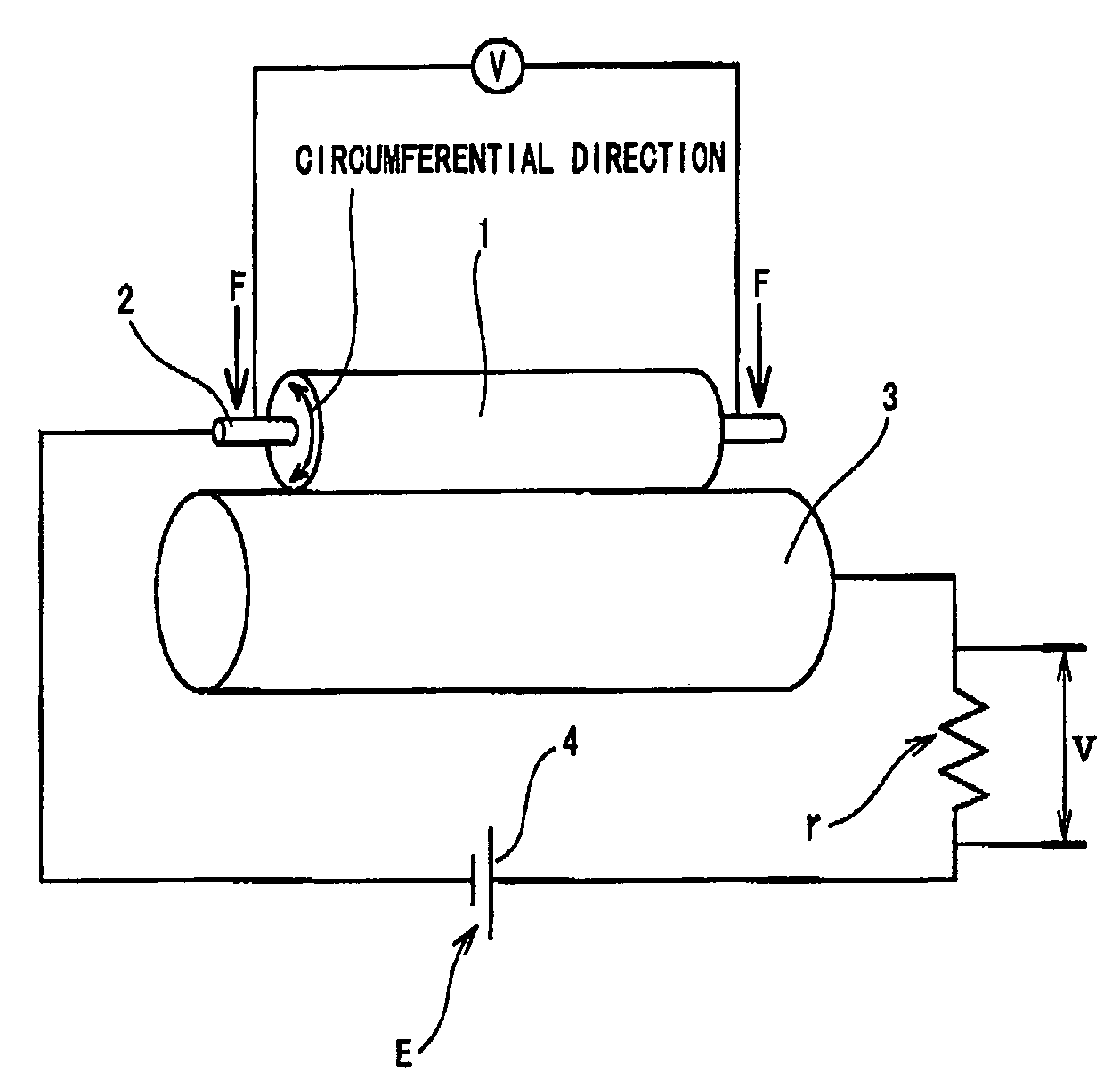
[0069]As shown in table 1, the value of common logarithm indicating the electric resistance of the conductive roller of each of the examples 1 through 16 fell within the scope of the present invention. The electrostatic capacity of each conductive roller at the frequency of 100 Hz fell within the scope of the present invention, namely, less than 50 pF. The conductive addition salt 1 was used in examples 1 through 6 and 16. The conductive addition salt 2 was used in the examples 7 through 10. The conductive addition salt 5 was used in the example 11. The conductive addition salt 3 was used in the example 12. The conductive addition salt 4 was used in the example 13. In this manner, the kind of the anion-containing salt having the fluoro group and the sulfonyl group was varied in the examples. The conductive elastic layer of each of the examples 14 and 15 did not contain any conductive addition salt.

[0070]The cations of the conductive addition salts 5, 3, and 4 contained in the conduc...


PUM


Abstract

A conductive roller including a core metal and a conductive elastic layer disposed on a peripheral surface of the core metal. The conductive roller has an electrostatic capacity not more than 50 pF at 100 Hz and an electric resistance not less than 105Ω nor more than 109Ω at an applied voltage 1000V. An electrostatic capacity C (L) at an alternating low frequency (L) and an electrostatic capacity C (H) at an alternating high frequency (H) satisfy the following relationship:
0<(C(L)−C(H))/(log10 Hz(H)−log10 Hz(L))<10.

Description

[0001]This Nonprovisional application claims priority under 35 U.S.C. § 119(a) on Patent Application No(s). 2002-332345 filed in Japan on Nov. 15, 2002, the entire contents of which are hereby incorporated by reference.BACKGROUND OF THE INVENTIONField of the Invention[0002]The present invention relates to a conductive roller. More particularly, the present invention relates to a conductive roller for use in the image-forming mechanism of electrophotographic apparatuses of an office appliance such as a printer, a copying apparatus, a facsimile, and an ATM. The present invention is intended to provide the conductive roller whose electrical characteristic is improved to suppress occurrence of toner dispersion.[0003]The following conductive rollers are used in the conductive mechanism of the electrophotographic image-forming apparatuses such as the printer, the electrophotographic copying apparatus, the facsimile, and the like: a charging roller for uniformly charging a photosensitive m...

Claims


Application Information

Patent Timeline
IPC IPC(8): B25F5/02G03G5/04F16C13/00G03G15/02G03G15/14
CPCG03G15/0233G03G2215/1614G03G2215/0861F16C13/00
Inventor UESAKA, KENICHIHATTORI, TAKAYUKIOCHI, JUN
Owner SUMITOMO RUBBER IND LTD
Why Eureka
Try Eureka