Stabilized interbody fusion system for vertebrae

a fusion system and interbody technology, applied in the field of interbody implants, can solve problems such as difficulty in keeping implants

Inactive Publication Date: 2007-02-06
SCIENTX
View PDF13 Cites 511 Cited by
  • Summary
  • Abstract
  • Description
  • Claims
  • Application Information

AI Technical Summary

Problems solved by technology

However, the applicant has identified a difficulty in keeping the implant in its ideal position within the intervertebral space to enable it to be anchored on the vertebrae to be mutually assembled through the screws.

Method used


Image

  • Stabilized interbody fusion system for vertebrae
  • Stabilized interbody fusion system for vertebrae
  • Stabilized interbody fusion system for vertebrae

Examples


Embodiment Construction

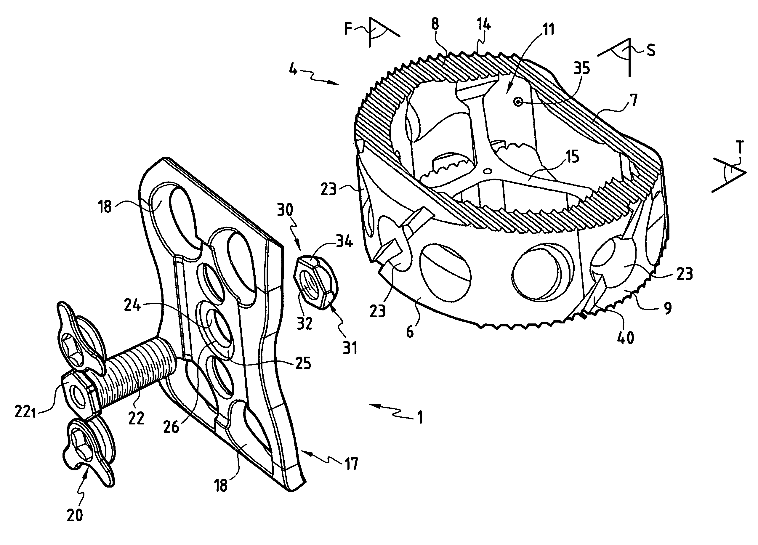
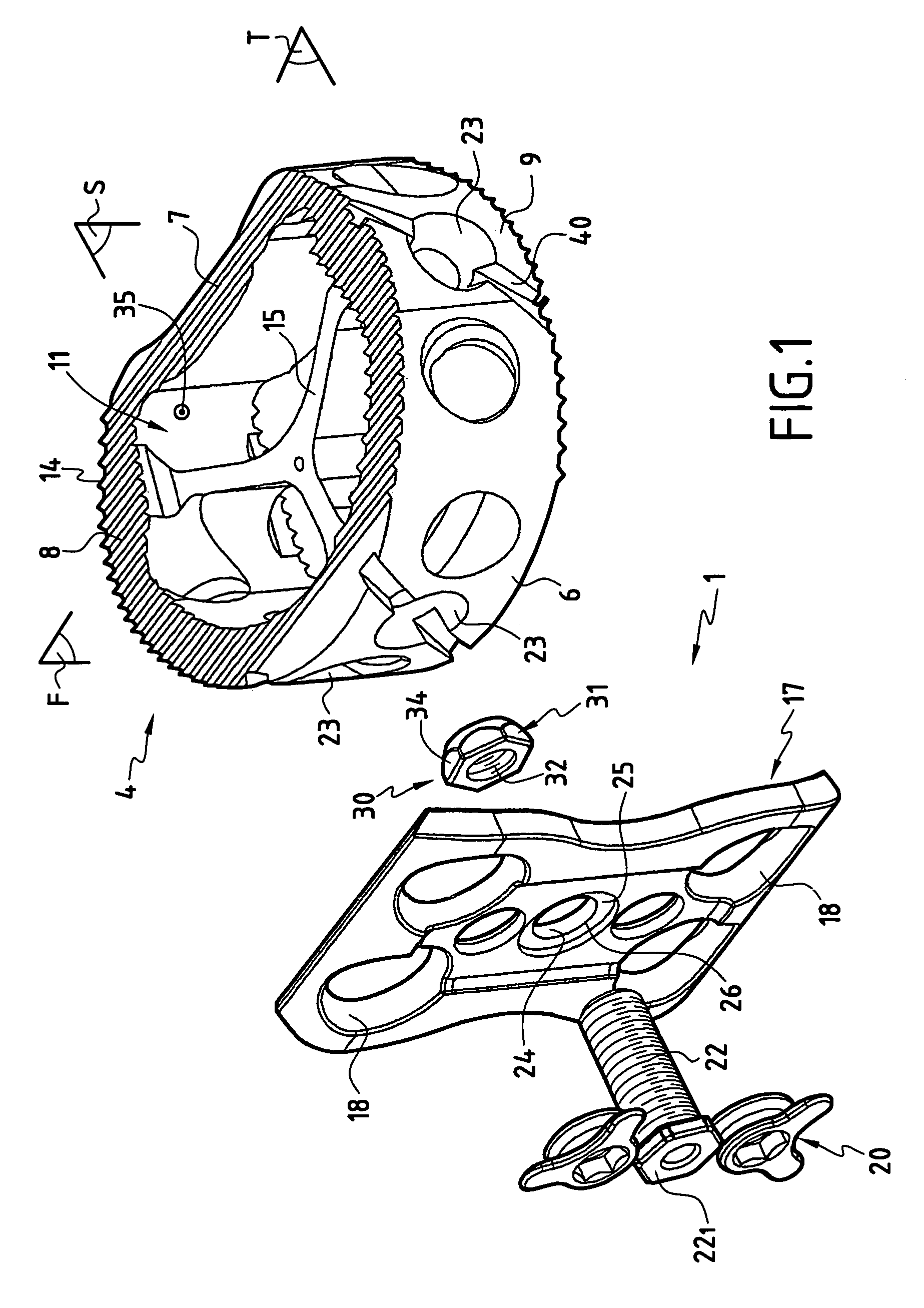
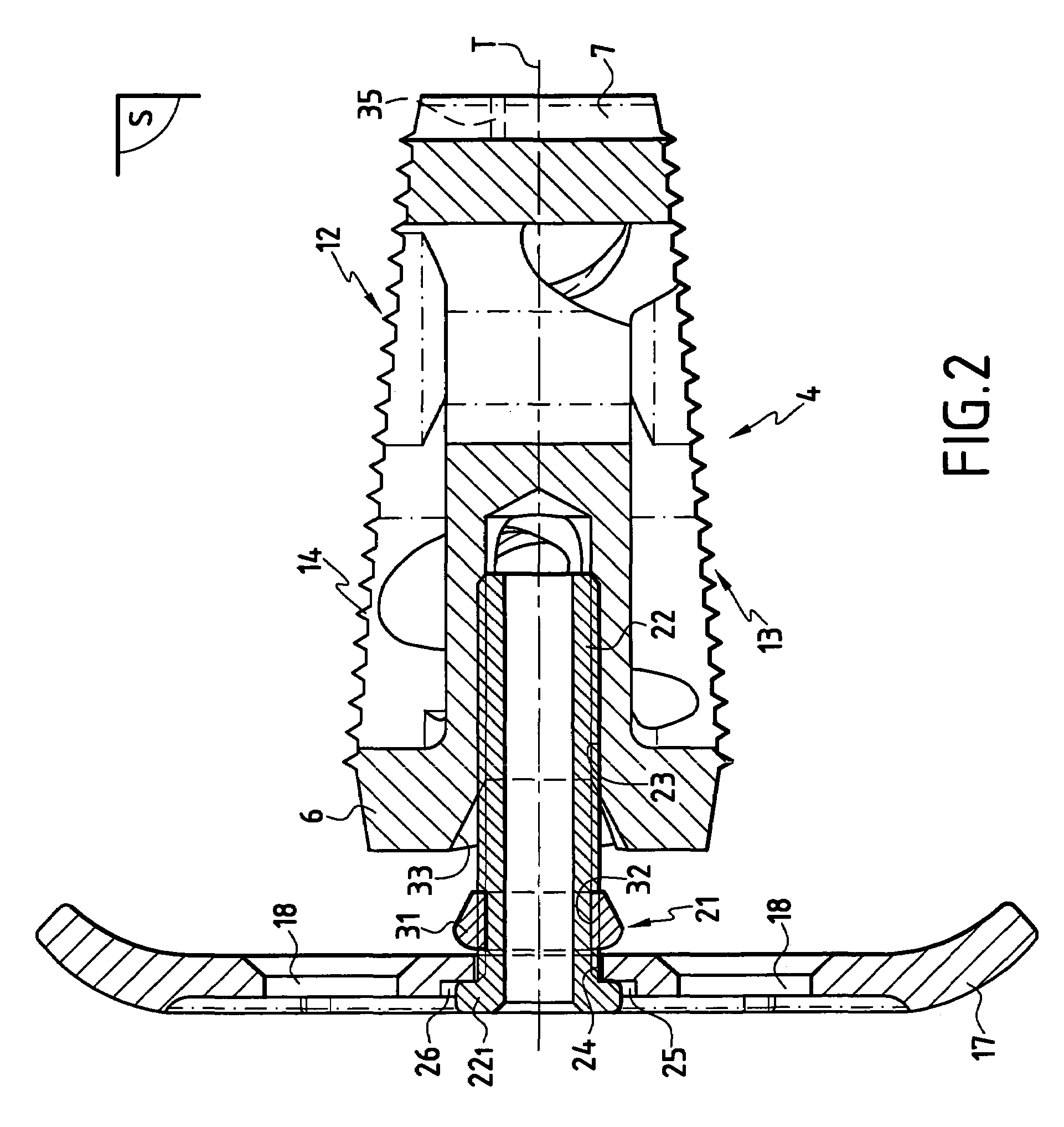
[0020]As is clear particularly in FIG. 1 to 3, the invention relates to a stabilized interbody fusion system 1 for two neighboring or nearby vertebrae 2, 3. The stabilized system 1 comprises an interbody implant 4 that will be inserted into the intervertebral space 5 delimited by the two vertebrae 2, 3. In one preferred embodiment of the invention as illustrated on the drawings, the implant 4 is made by a cage with a transverse wall 6 called the anterior wall, and a transverse wall 7 called the posterior wall, connected to each other by connecting walls 8, 9. The walls 6 to 9 of the cage are perpendicular to a transverse plane T that is perpendicular to a sagittal plane S passing through the anterior wall 6 and the posterior wall 7. In the transverse plane T, the anterior wall 6 has a convex curvature and extends on each side by the connecting walls 8, 9, which also have convex curvatures and are connected to each other by the posterior wall 7 with a concave curvature to leave the v...


PUM


Abstract

The invention concerns a stabilized interbody fusion system for vertebrae, of the type comprising an interbody implant (4) designed to be inserted in the intervertebral space defined between two neighboring vertebrae to be mutually secured, so as to restore the height and the angle of the lordosis of the vertebral segment defined by the two neighboring vertebrae and a stabilizing plate (17) provided, at each of its ends, with at least a passage hole (18) for an anchoring screw, the plate (17) and the implant (4) being provided with mutual assembly means, such that after assembly, the stabilizing plate (17) extends on each side of the implant to enable the stabilizing plate to be anchored on the neighboring vertebrae through the screws, characterized in that it comprises spacing means (30), interposed between the stabilizing plate (17) and the implant (4), to enable the stabilizing plate to be positioned at a specific distance relative to the implant.

Description

FIELD OF THE INVENTION[0001]The present invention relates to interbody implants to be inserted in the intervertebral space defined between two neighboring vertebrae after intervertebral disk excision, in order to restore the intervertebral space and to form bone fusion between the said neighboring vertebrae.[0002]More precisely, the domain of the invention is lumbar type interbody implants to restore the height and the angle of the lordosis of the vertebral segment defined by two neighboring lumbar vertebrae to be mutually secured.[0003]More precisely, the purpose of the invention is an interbody implant, called a secured implant, in other words provided with the means of anchoring the implant in its insertion site, to prevent it from becoming mobile.BACKGROUND ART[0004]There are several stabilized interbody fusion systems for vertebrae known in the state of the art. For example, there is a known stabilized system comprising an interbody implant to be inserted in the intervertebral ...

Claims


Application Information

Patent Timeline
Patent Type & Authority Patents(United States)
IPC IPC(8): A61F2/44A61B17/70A61B17/80A61B17/86A61F2/00A61F2/02A61F2/30A61F2/46
CPCA61B17/7059A61F2/447A61F2/4611A61F2250/0098A61B17/86A61F2/442A61F2002/3008A61F2002/30266A61F2002/30433A61F2002/30538A61F2002/3055A61F2002/30578A61F2002/30787A61F2002/3082A61F2002/30904A61F2002/4475A61F2002/4627A61F2220/0041A61F2230/0082A61F2250/0006A61F2250/0007A61B17/8042A61F2002/30593
Inventor FIERE, VINCENTFAYADA, PAULTAZIAUX, JEAN-PAUL
Owner SCIENTX
Why Eureka
Try Eureka