
System and method for incorporating graphics into absorbent articles

a technology of absorbent articles and graphics, applied in the direction of mechanical control devices, process and machine control, instruments, etc., can solve the problems of affecting the aesthetics of the product, requiring complex feed-back control systems, and not desirabl

Inactive Publication Date: 2007-02-06
FIRST QUALITY RETAIL SERVICES
View PDF16 Cites 32 Cited by
  • Summary
  • Abstract
  • Description
  • Claims
  • Application Information

AI Technical Summary

Benefits of technology

Enables accurate and aesthetically pleasing placement of graphics on absorbent articles without the need for reference markers, reducing production complexity and costs while maintaining high precision in graphic placement.

Problems solved by technology

This is so because the reference markers employed in prior techniques need to be sensed downstream in the production line to provide error correction, requiring complex feed-back control systems.
However, the inclusion of the reference markers on the final assembled product can detract from the aesthetics of the product and are therefore not desirable.
The so-called conventional techniques are said not to be capable of withstanding severe process disturbances.
These disturbances, described as start-ups, splices within various web materials, and non-uniform stretching of web material caused by a non-uniform winding of the web materials onto the associated supply roll, are said to cause an improper placement of a significant number of patches and thereby increase cost and waste.
Furthermore, the '543 patent states that in conventional techniques in which the detector is mounted a large distance from the cutter, the individual sets of print design graphics may not be exactly equally spaced, and the relative position of the patch graphics measured at the detector may not accurately represent the relative position of the patch graphics when the web material reaches the cutting mechanism.
Due to this, the '543 patent recognizes that the greater the distance between the detector and the cutting mechanism, the larger the errors can be.
Indeed, without the reference marker on the final absorbent article in the '543 patent, feedback control is effectively eliminated from the system described in the '543 patent, and concomitantly process disturbances evidently will be permitted to cause the improper cutting and / or placement of the graphic, leading to a graphic that is neither aesthetically pleasing nor congruously entire.
But even though the so-called conventional techniques described in the '543 patent do not employ the reference marker later in the process line, they still apparently leave the reference marker on the final, assembled absorbent article.
As noted previously, the reference markers in some instances are aesthetically displeasing, so leaving them on the final assembled absorbent article can detract from the presentation of the article.
The inclusion of the reference marker(s) in the assembled product can detract from the aesthetic qualities of the final absorbent article, and the feed-back control can overly complicate the production line.
Further, the assembly and layering of the component parts in the machine direction, as shown in the prior art, limits the flexibility of the production line to incorporate a variety of different graphics into the integrated absorbent article.
In addition to the shortcomings described above, the prior art attempts at placing decorative graphics on absorbent garments are both expensive and, because of their complexity, sensitive to equipment and programming failures.

Method used


Image

  • System and method for incorporating graphics into absorbent articles
  • System and method for incorporating graphics into absorbent articles
  • System and method for incorporating graphics into absorbent articles

Examples


Embodiment Construction

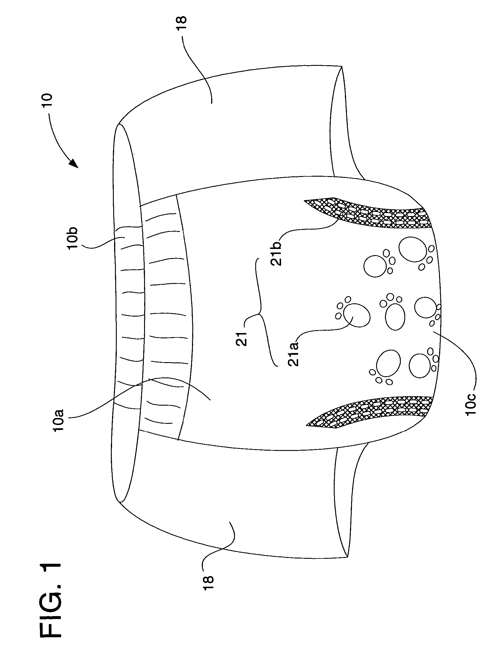
[0031]As used herein, the terms “absorbent garment,”“garment,”“absorbent article” and “article” refer to garments that absorb and contain exudates, and more specifically, refers to garments that are placed against or in proximity to the body of the wearer to absorb and contain various exudates discharged from the body. A non-exhaustive list of examples of absorbent articles includes diapers, diaper covers, disposable diapers, training pants, feminine hygiene products, and adult incontinence products. The term “disposable absorbent garment” refers to absorbent garments that are intended to be discarded or partially discarded after a single use (i.e., they are not intended to be laundered or otherwise restored or reused).

[0032]The present invention can be used with all of the foregoing classes of absorbent articles, without limitation, whether disposable or otherwise. These classifications are used interchangeably throughout the specification, but are not intended to limit the claimed...


PUM

PropertyMeasurementUnit
diameteraaaaaaaaaa
angular velocityaaaaaaaaaa
diameteraaaaaaaaaa

Abstract

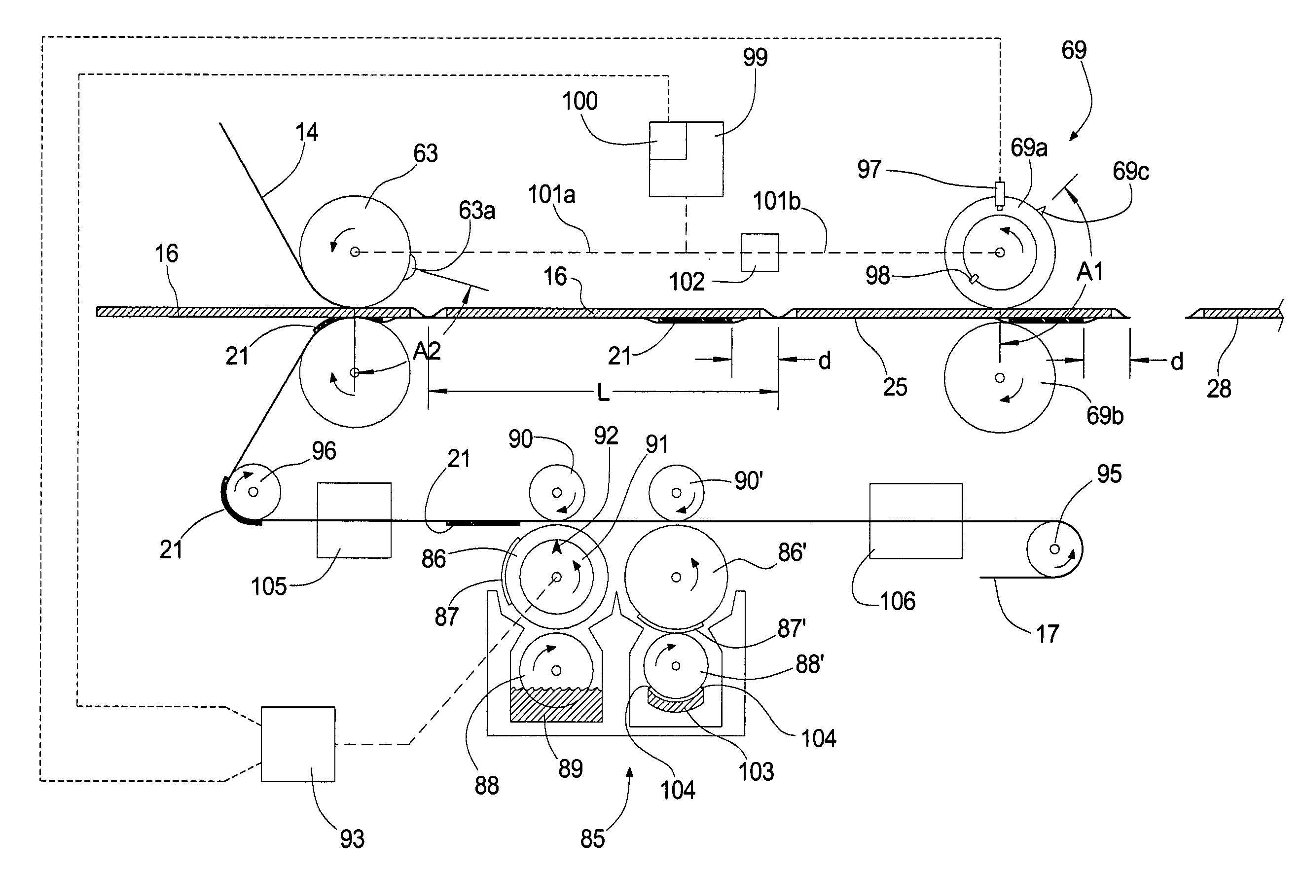
A method for incorporating graphics into absorbent articles. The method involving: providing a moving substrate to a print cylinder; sensing a line speed reference signal from a line speed target machinery component; rotating the print cylinder at a predetermined speed, based on the line speed reference signal, to thereby print a series of graphics on the moving substrate at a predetermined distance frequency; sensing a phase difference signal from a phase target machinery component; and setting an actual print cylinder phase angle, based on the phase difference signal, to approximate a predetermined phase angle to thereby position the series of graphics on the moving substrate at a series of desired graphics locations. A system for executing the method and garments produced from the method and system are also provided.

Description

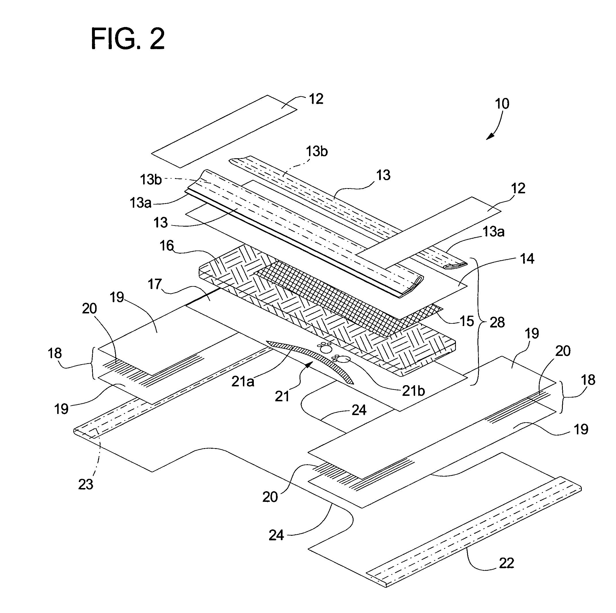
FIELD OF THE INVENTION[0001]The present invention relates to disposable absorbent articles, and more particularly to disposable absorbent articles having graphics thereon, and processes for making the same.BACKGROUND OF THE INVENTION[0002]Traditionally, disposable absorbent articles, such as infant diapers or training pants, adult incontinence products and other such products, are constructed with a moisture-impervious outer backing sheet (or “backsheet”), a moisture-pervious body-contacting inner liner sheet (or “topsheet”), and a moisture-absorbent core (or “absorbent core”) sandwiched between the liner sheet and the backing sheets. These disposable absorbent articles oftentimes include additional features such as elastic waist bands, elastic leg bands, and stretchable side panels. Further, decorative graphics can be incorporated into the disposable absorbent article for aesthetic and functional purposes.[0003]Disposable absorbent articles are generally assembled on an automated p...

Claims


Application Information

Patent Timeline
Patent Type & Authority Patents(United States)
IPC IPC(8): B32B37/20A61F13/15A61F13/42B41F13/12
CPCA61F13/15772A61F13/42B41F13/12Y10T156/1052A61F2013/8497Y10T83/528
Inventor VERGONA, JOSEPH B.
Owner FIRST QUALITY RETAIL SERVICES
Learn More