Activity-based battery monitor with a universal current measuring apparatus

a technology of current measurement and battery monitor, which is applied in the direction of instruments, base element modifications, material analysis, etc., can solve the problems of resistance to change, inability to easily remove intercell connectors, and welded intercell connectors on battery posts, etc., and achieve the effect of minimal labor

Inactive Publication Date: 2007-02-06
POWER DESIGNERS USA
View PDF26 Cites 13 Cited by
  • Summary
  • Abstract
  • Description
  • Claims
  • Application Information

AI Technical Summary

Benefits of technology

[0008]In order to overcome the limitations of DC shunts described above in accordance with the invention, accurate current measurements can be made using an existing conductive element or link in the system or an intercell connector in a battery application. Since a conductive link or intercell connector is made of a highly conductive material (e.g., lead or copper), the current can be obtained by measuring the voltage drop across the conductive element and dividing it by the resistance of that element. Using a conductive element or intercell connector as the current sense device is advantageous as it allows for easy addition of current measurement capabilities with minimal labor and leads to wider adoption of intelligent systems.

Problems solved by technology

The I2R loss causes the shunt temperature to rise, causing its resistance to change.
In many applications, installing a DC shunt is not a straightforward task.
For example, in flooded Lead-Acid batteries, the intercell connectors are welded on the battery posts and cannot be easily removed.
This is a labor-intensive process, especially if it is to be performed in the field.
In addition, if the battery has more than two posts (more than one intercell connector), replacing only one intercell connector with a shunt will cause the currents between the shunt and the remaining intercell connector to be unequal due to the large mismatch in resistance.

Method used


Image

  • Activity-based battery monitor with a universal current measuring apparatus
  • Activity-based battery monitor with a universal current measuring apparatus
  • Activity-based battery monitor with a universal current measuring apparatus

Examples


Embodiment Construction

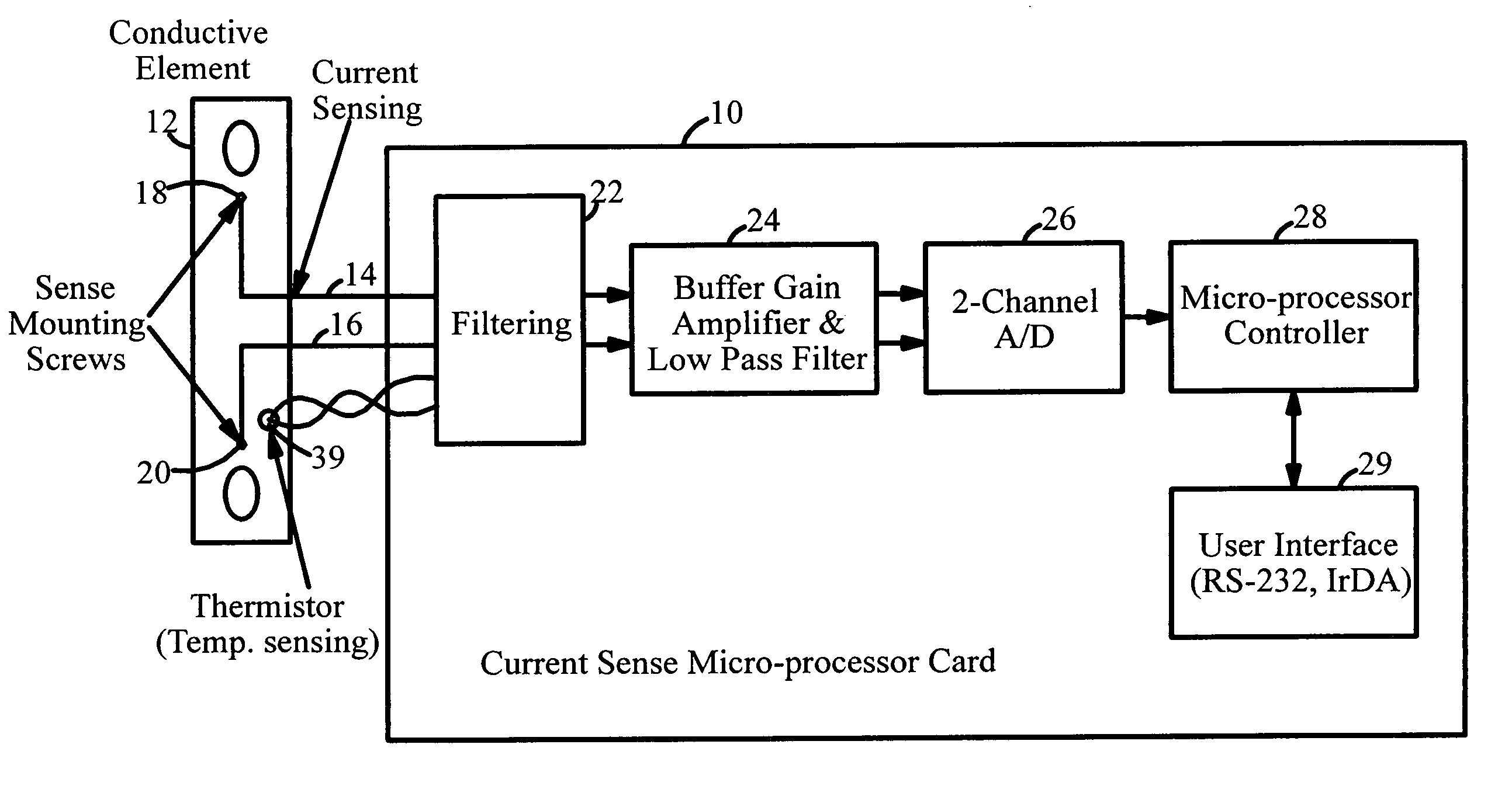
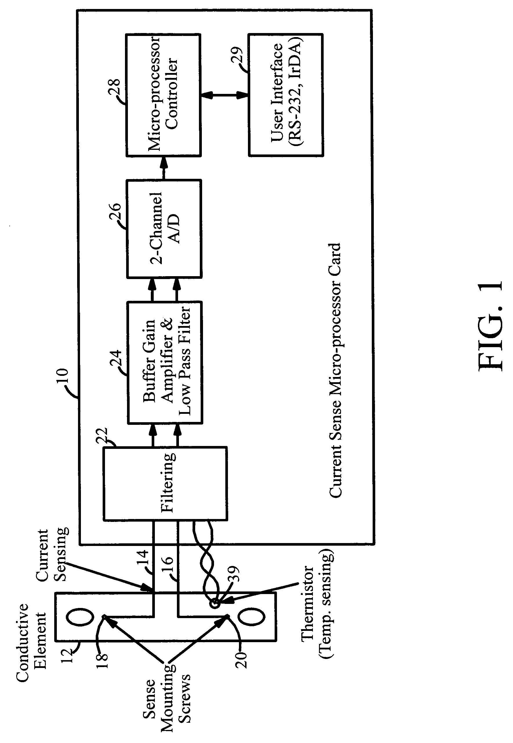
[0021]FIG. 1 illustrates a universal current measuring apparatus 10 that measures the current of any conductive element link. The apparatus 10 is connected to a conductive element 12 by two wires 14 and 16. The two wires 14 and 16 are attached across the conductive element link using self-tapping screws 18 and 20. The screws 18 and 20 can be, for example, a distance of 2 to 3 inches apart.

[0022]The separation of the two wires 14 and 16 along the conductive element 12 results in a voltage drop which is proportional to the resistance in between the two sense leads. The distance between the sense leads can be adjusted to obtain an approximate target voltage drop (typically, a few millivolts) at a given current. For example, in a battery application, if an intercell connector is used to measure current, connecting the sense lead 2 inches apart across an intercell connector may yield a 50 mV voltage drop at 1000 A nominal current. Since the spacing may not be exact from one system to ano...


PUM

PropertyMeasurementUnit
distanceaaaaaaaaaa
voltage dropaaaaaaaaaa
temperatureaaaaaaaaaa

Abstract

A battery monitoring apparatus that obtains a current measurement for a current in a conductive element. The battery monitoring apparatus includes conductive lines configured to couple to a conductive element having an electrical current, a filter coupled to the conductive lines and configured to filter noise from a signal derived from a voltage difference between the conductive lines, an analog-to-digital converter that converts the signal filtered by the filter and outputs a digital signal, and a controller that receives the digital signal from the analog-to-digital converter.

Description

FIELD OF THE INVENTION[0001]The present invention pertains generally to the field of battery condition monitoring and management and, more particularly, to a universal current measuring apparatus for use with a battery monitor.BACKGROUND OF THE INVENTION[0002]Current shunts (DC shunts) are widely used in many applications to measure the device or system current for metering and control applications. Generally, a conventional DC shunt is a four terminal device that is constructed using special metal elements having a known resistance, RDC. The resistive elements are welded between two posts or terminals (power terminals) that are used to interconnect the shunt in line with the main system or device current. Two separate terminals are used to sense the current flow through the resistive elements. The current measurement is made by measuring the voltage across the sense terminals and dividing that by the shunt resistance, namely[0003]ID⁢⁢C=VD⁢⁢CRD⁢⁢C.[0004]In order to reduce the unwant...

Claims


Application Information

Patent Timeline
Patent Type & Authority Patents(United States)
IPC IPC(8): G01N27/416G01R1/20G01R31/36
CPCG01R31/3648G01R1/203G01R31/3606G01R35/005G01R31/3658G01R31/382G01R31/396
Inventor KUTKUT, NASSER H.BROBST, DAVIDSLAVOV, HRISTO
Owner POWER DESIGNERS USA
Why Eureka
Try Eureka