
Method of producing traps in a print page

a trap and print page technology, applied in the field of digital image processing in reproduction technology, can solve the problems of unprinted strips produced as a result, errors which are produced, and register errors in the printing machine, and achieve the effect of reducing processing time and small amount of memory spa

Inactive Publication Date: 2007-02-06
HEIDELBERGER DRUCKMASCHINEN AG
View PDF19 Cites 8 Cited by
  • Summary
  • Abstract
  • Description
  • Claims
  • Application Information

AI Technical Summary

Benefits of technology

This approach significantly reduces processing time and memory requirements, enabling efficient trap calculation with run-length encoded data, thus overcoming the limitations of previous methods.

Problems solved by technology

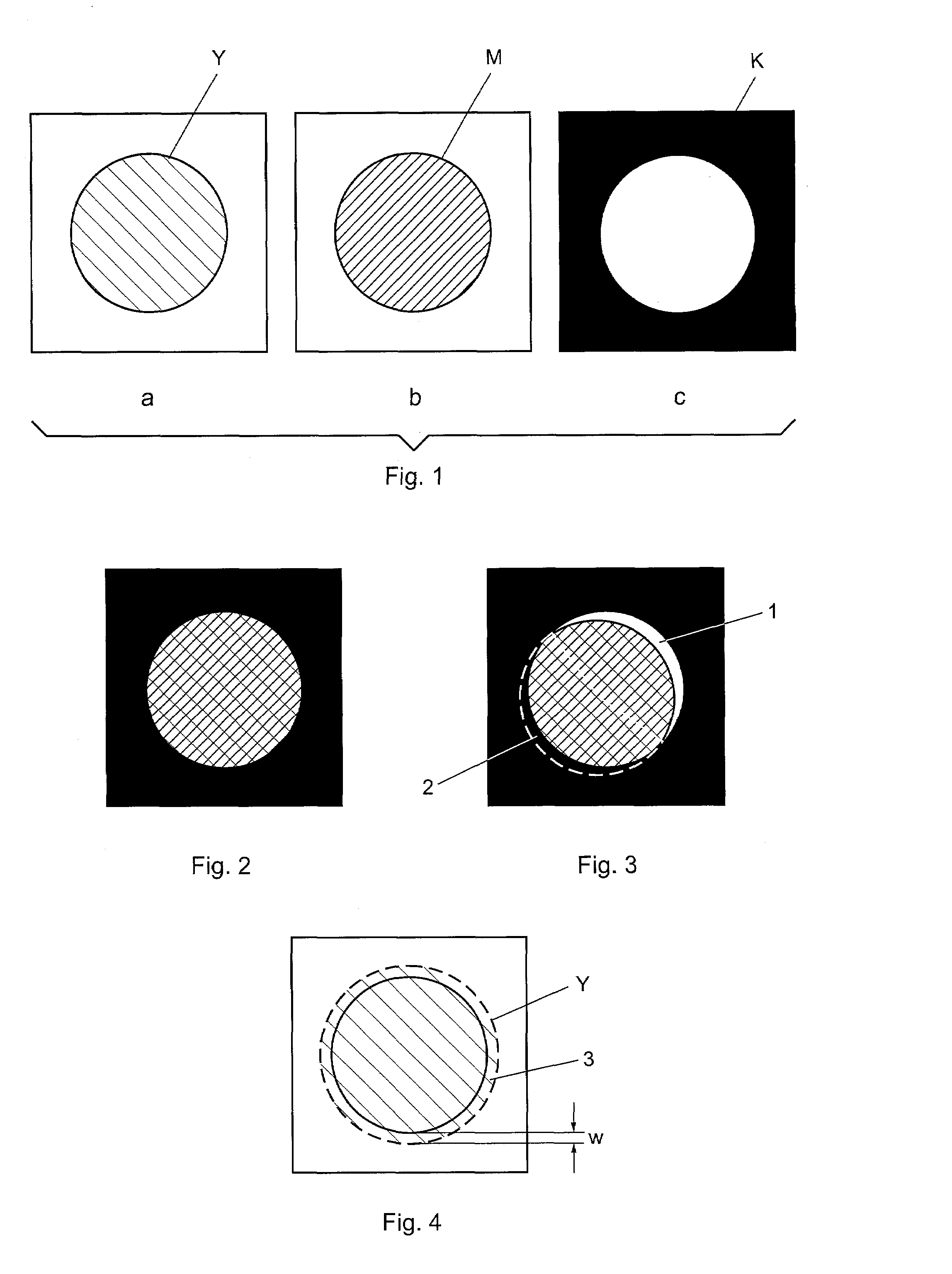
One problem in printing technology is the register errors in the printing machine, that is to say errors which are produced because the printing inks in the printing units, through which the paper runs successively, are not overprinted exactly coincidentally but are shifted somewhat in relation to one another.
ced. Since the unprinted strip 1 has the color of the paper, that is to say is generally white, it stands out very strongly between the red and the black color and is felt to be disrup
FIG. 3. However, even in the case of a smaller displacement, such as occurs during the practical printing operation, the unprinted strips produced as a result are very disruptive and it is necessary for countermeasures to be taken in order to eliminate or reduce thes
However, this is complicated and expensive, and an improved control system cannot be retrofitted to every older printing machine either.
Such methods require a great deal of computing effort.
Further computing effort arises in the case of the methods of the prior art as a result of the calculation of the trap.
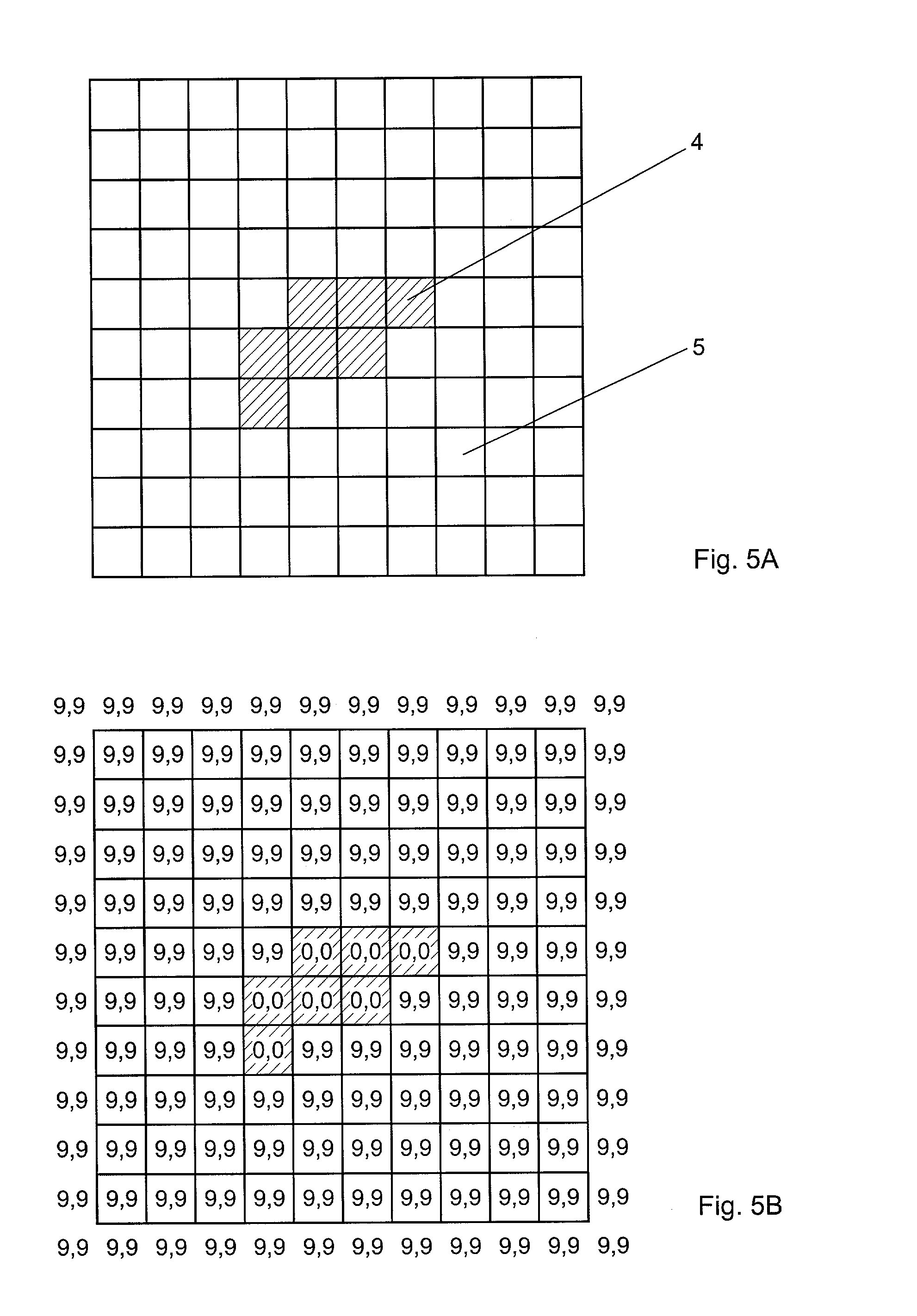
The method described for determining traps with the aid of distance mapping has the disadvantage that it can be carried out only with image data which is present in the form of an image point matrix.
It is obvious that the processing time for high-resolution graphics / text image data becomes so great that the method of distance mapping according to the prior art cannot be used economically.

Method used


Image

  • Method of producing traps in a print page
  • Method of producing traps in a print page
  • Method of producing traps in a print page

Examples


Embodiment Construction

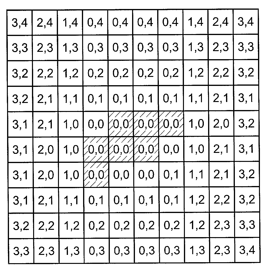
[0067]According to the method of the invention, distance vectors are in each case determined for the starting point and the end point of the run lengths and are extrapolated as a function of the distance vectors of the adjacent run lengths. FIG. 8 shows a run length 6 which is located in a region of the color 1. The run length 6 describes a sequence of image points of the same color from a starting point A as far as an end point E. A distance vector DA describes the shortest distance of the starting point A from a closest region of another color 2. Likewise, a distance vector DE describes the shortest distance of the end point E from a closest region of another color. The distance vectors in each case have an x component and a y component. Here, the components are designated (DAx, DAy) for the distance vector DA and (DEx, DEy) for the distance vector DE. The magnitudes of the distances are calculated from the components, for example as the Euclidian distance.

|DA|=√{square root over ...


PUM


Abstract

Traps are produced at color boundaries in a print page that is present in the form of run-length encoded image data, by way of distance mapping. Distances of the run lengths to an adjacent color are determined without decoding the run lengths into a pixel matrix, and the traps are produced on the basis of the distances thus determined. For this purpose, distance vectors are determined for the starting point and for the end point of a run length. The distance vectors are in each case recalculated from the comparison with the distance vectors of adjacent run lengths. The new values of the distance vectors replace the previous values of the distance vectors if the magnitudes of the distances of the new values are less than the magnitudes of the distances of the previous values.

Description

BACKGROUND OF THE INVENTIONField of the Invention[0001]The invention lies in the field of digital image processing in reproduction technology and pertains to a method of producing traps at color boundaries in a printed page. Such traps or overfill frames serve to reduce the disruptions caused by register errors in the printing machine, that is to say the errors which arise because the printing inks are not overprinted with exact coincidence, but are shifted somewhat in relation to one another.[0002]In reproduction technology, printing originals for printed pages are produced which contain all the elements to be printed, such as text, graphical objects and images. In the case of electronic production of the printing originals, these elements are present in the form of digital data. For an image, the data are produced, for example, by the image being scanned point by point and line by line in a scanner, each image point being broken down into color components and the color values of t...

Claims


Application Information

Patent Timeline
Patent Type & Authority Patents(United States)
IPC IPC(8): G06K15/00H04N1/41H04N1/419H03M7/46H04N1/58
CPCH04N1/58
Inventor KOHN, MICHAEL
Owner HEIDELBERGER DRUCKMASCHINEN AG
Learn More