Fuel injector

a fuel injector and fuel technology, applied in the direction of valve operating means/release devices, machines/engines, magnetic bodies, etc., can solve the problems of difficult closing of field lines, interference with achieving high attraction forces, and complicated design features of additional components, so as to improve the long-term stability of the elastomer ring

Inactive Publication Date: 2007-02-13
ROBERT BOSCH GMBH
View PDF15 Cites 5 Cited by
  • Summary
  • Abstract
  • Description
  • Claims
  • Application Information

AI Technical Summary

Benefits of technology

[0007]The fuel injector according to the present invention has the advantage over the related art that the elastomer ring is supported axially over its full surface. Thus, there cannot be any edge pressure on the elastomer ring. This improves the long-term stability of the elastomer ring.
[0009]This is achieved in that the longitudinal axis of the fuel channel is inclined to the longitudinal axis of the armature so that the fuel channel opens radially outside the elastomer ring. In this way, the elastomer ring is also supported over its entire surface on an end face of the armature. In this embodiment, no vibration is induced in the elastomer ring by fuel flowing past it.
[0010]The supporting ring may advantageously have an integrally molded shoulder. Therefore, the elastomer ring is also supported radially and is protected from vibration induced by the fuel flowing past it. Accordingly, the end face of the armature may have a projection which provides radial protection.

Problems solved by technology

One disadvantage is the complicated design featuring an additional component.
The large-area elastomer ring is also a disadvantage for the variation of the magnetic field and makes it difficult for the field lines to close and thus interferes with achieving high attraction forces in the opening movement of the fuel injector.
One disadvantage of the embodiment described there is the additional complexity and space required.
However, since the axial position of the armature with respect to the valve needle is completely undefined due to the free mobility of the armature with respect to the valve needle, rebound pulses are prevented only to a limited extent.
In particular, the design of the fuel injector known from U.S. Pat. No. 5,299,776 does not prevent the armature from striking the stop facing the valve closing body in the closing movement of the fuel injector and transmitting its momentum abruptly to the valve needle.
This abrupt transfer of momentum can cause additional rebound pulses of the valve closing body.
However, then the problem arises that a bore through the armature is necessary to supply fuel to the valve seat face.
This results in irregular pressure on the elastomer ring and finally the bore edges result in the destruction of the elastomer ring due to edge pressure.
Furthermore, the vibrations are induced in the unsupported elastomer ring, which also contributes to destruction by the bore edges.

Method used


Image

  • Fuel injector
  • Fuel injector
  • Fuel injector

Examples


Embodiment Construction

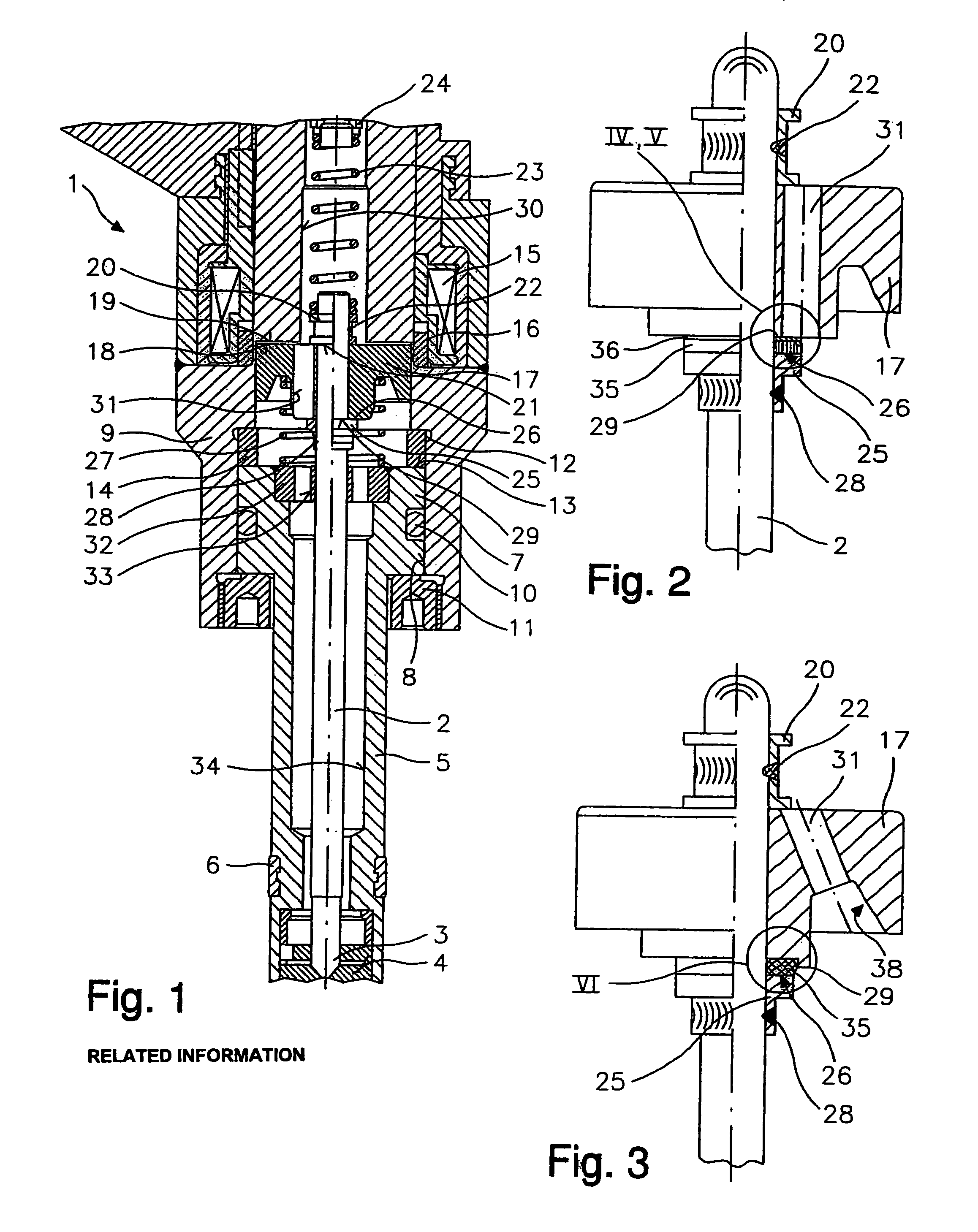
[0019]FIG. 1 shows a detail of a generic fuel injector 1 in a sectional diagram to better explain the present invention. Fuel injector 1 injects fuel into an internal combustion engine having fuel mixture compression and spark ignition. The embodiment illustrated here is a high pressure fuel injector opening inward for direct injection of fuel into the combustion chamber of the internal combustion engine.

[0020]Fuel injector 1 has a valve closing body 3 which is connected in one piece to a valve needle 2 in this embodiment and works together with a valve seat face designed on a valve seat body 4 to form a sealing seat. Valve seat body 4 is connected to a tubular valve seat carrier 5 which can be inserted into a receiving bore of a cylinder head of the internal combustion engine and is sealed with respect to the receiving bore by a gasket 6. On its inlet end 7, valve seat carrier 5 is inserted into a longitudinal bore 8 of a housing body 9 and is sealed with respect to the housing bod...


PUM


Abstract

A fuel injector for fuel injection systems of internal combustion engines, having a valve needle which works together with a valve seat face to form a sealing seat, has an armature acting on the valve needle. The armature is movably guided on the valve needle and is damped by an elastomer ring made of an elastomer. The armature has at least one fuel channel for supplying fuel to the sealing seat. A flat supporting ring which axially supports the elastomer ring in the area of the outlet end of the fuel channel is arranged between the elastomer ring and the armature.

Description

CROSS-REFERENCE TO RELATED APPLICATIONS[0001]This application is a division of prior U.S. patent application Ser. No. 09 / 868,681 filed on Sep. 24, 2001, now U.S. Pat. No. 6,799,734, which is a national stage application of PCT International Application No. PCT / DE00 / 03700 filed on Oct. 21, 2000, each of which is expressly incorporated herein in its entirety by reference thereto.FIELD OF THE INVENTION[0002]The present invention relates to a fuel injector.BACKGROUND INFORMATION[0003]U.S. Pat. No. 4,766,405 describes a fuel injector having a valve closing body connected to a valve needle and working together with a valve seat face designed on a valve seat body to form a sealing seat. For electromagnetic operation of the fuel injector, a solenoid works together with an armature connected in a friction-locked manner to the valve needle. An additional mass is provided in the form of a cylinder around the armature and the valve needle and is connected to the armature by an elastomer layer. ...

Claims


Application Information

Patent Timeline
Patent Type & Authority Patents(United States)
IPC IPC(8): B05B1/30F02M51/06F02M61/12F02M61/16F02M63/00
CPCF02M51/0685F02M61/12Y10S239/90F02M2200/306F02M59/46
Inventor HANS, WALDEMAR
Owner ROBERT BOSCH GMBH
Why Eureka
Try Eureka