
Device for protecting medical apparatus

a technology for medical devices and protective devices, applied in separation processes, liquid degasification, filtration separation, etc., can solve the problems of increased costs, poor security level, and loss of protective functions of membranes, and achieves simple and economical, high degree of security, and extreme ease and reliability.

Active Publication Date: 2007-02-13
GAMBRO LUNDIA AB
View PDF31 Cites 15 Cited by
  • Summary
  • Abstract
  • Description
  • Claims
  • Application Information

AI Technical Summary

Benefits of technology

The present invention provides a device that overcomes the drawbacks of prior art, is simple and economical to manufacture, and can guarantee a high degree of security against contamination by infectious agents. The device is also easy to transmit pressure signals from the extracorporeal circuit and is relatively small. The invention includes an intermediate portion made in a single piece with a central opening for gas passage and two hydrophobic membranes acting as aseptic barriers. The device is constructed by a single ultrasonic welding operation.

Problems solved by technology

One of the drawbacks of the known devices is their poor security level: the protective function of the membrane can be lost due to micro-lesions in the membrane itself, or imperfections, even microscopic, in the seal around the perimeter edge of the membrane, which edge is sealed and lies between two plastic elements bearing the two tubular connectors, along an ultrasonic plastic welding zone which, apart from solidly joining the plastic elements and the membrane, also guarantees the seal.
This solution, however, leads to increases in costs, due to the need to realize two distinct ultrasonic welding processes, one for each device, and also due to the need subsequently to realize a connection to the fluid line of the two devices.

Method used


Image

  • Device for protecting medical apparatus
  • Device for protecting medical apparatus
  • Device for protecting medical apparatus

Examples


Embodiment Construction

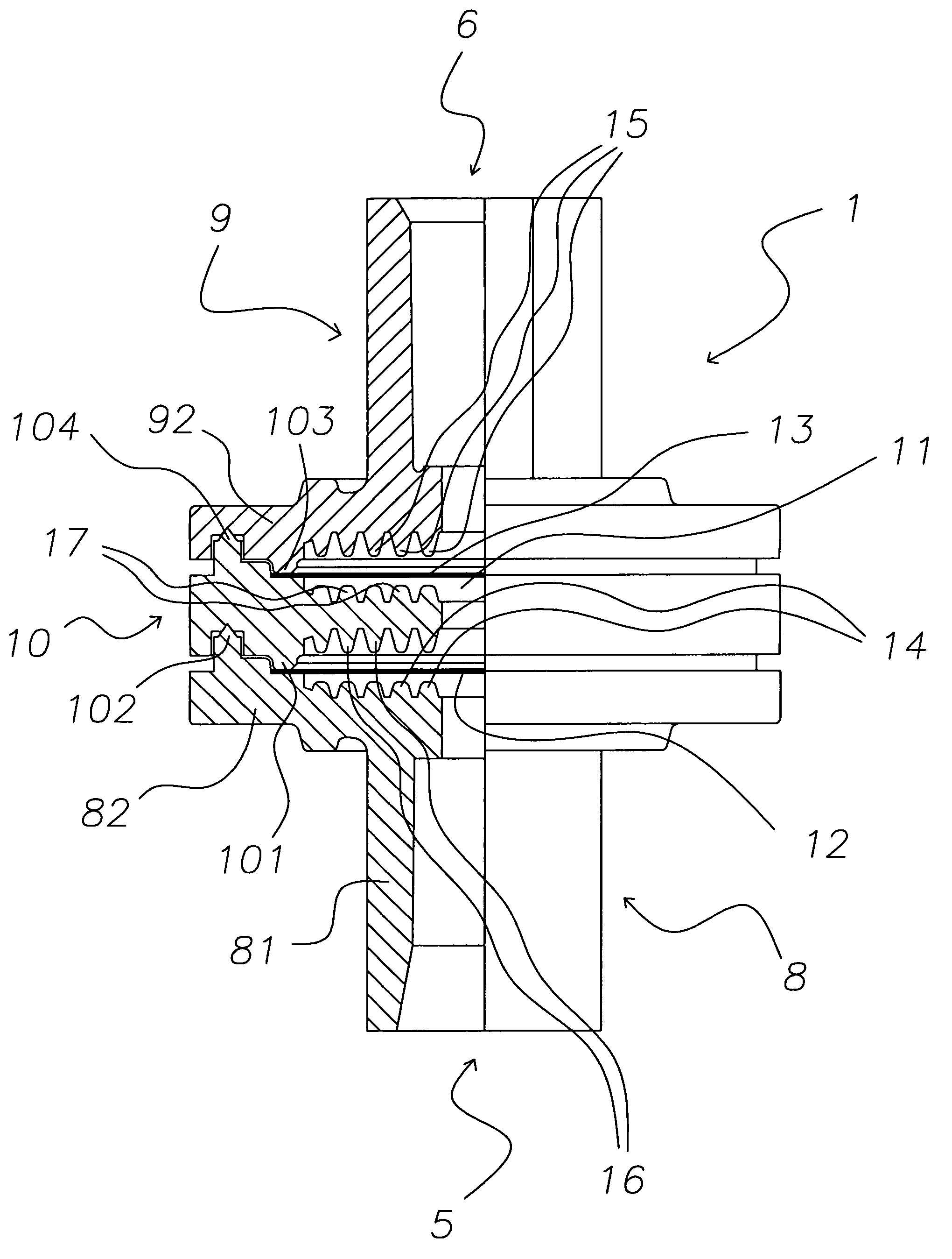
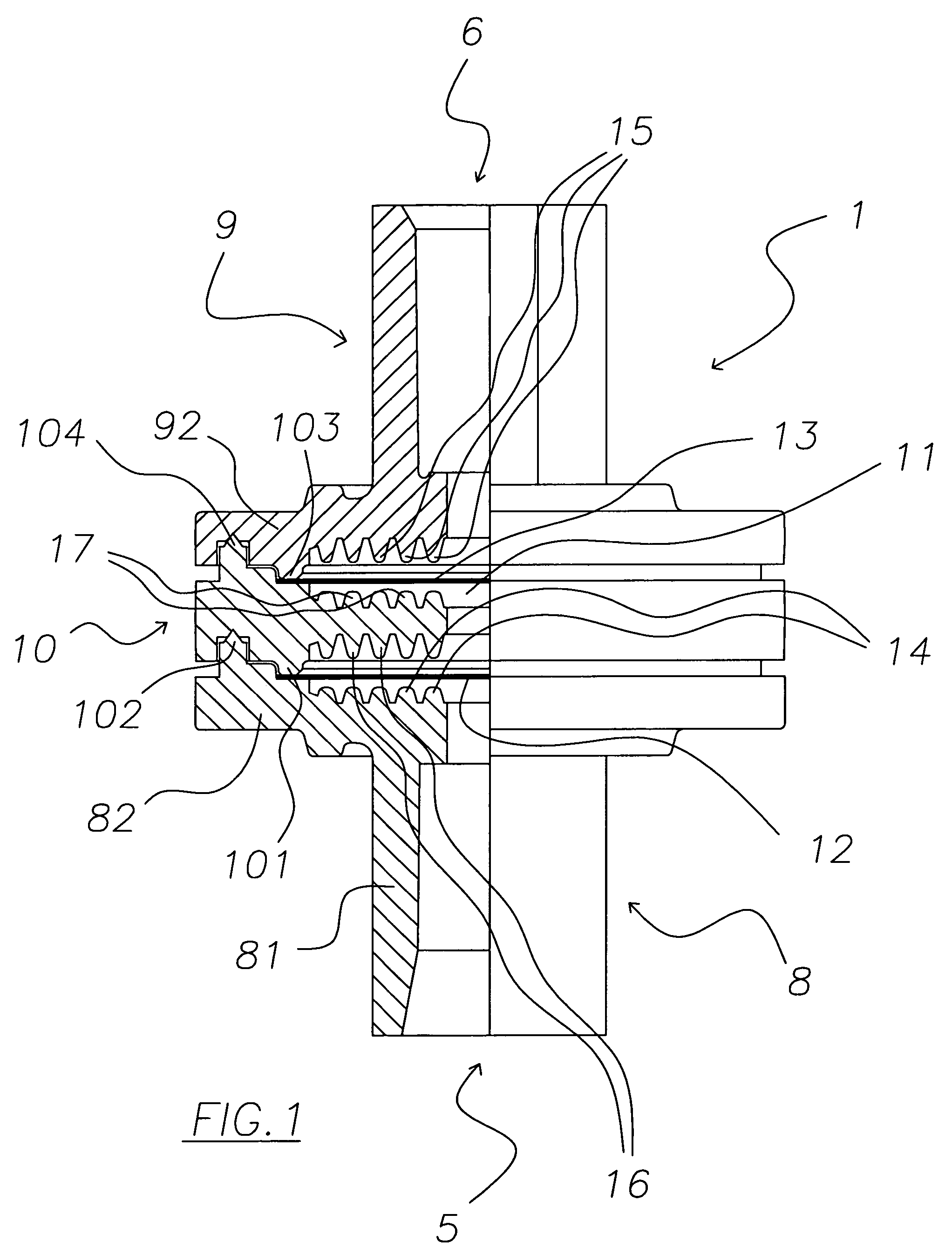
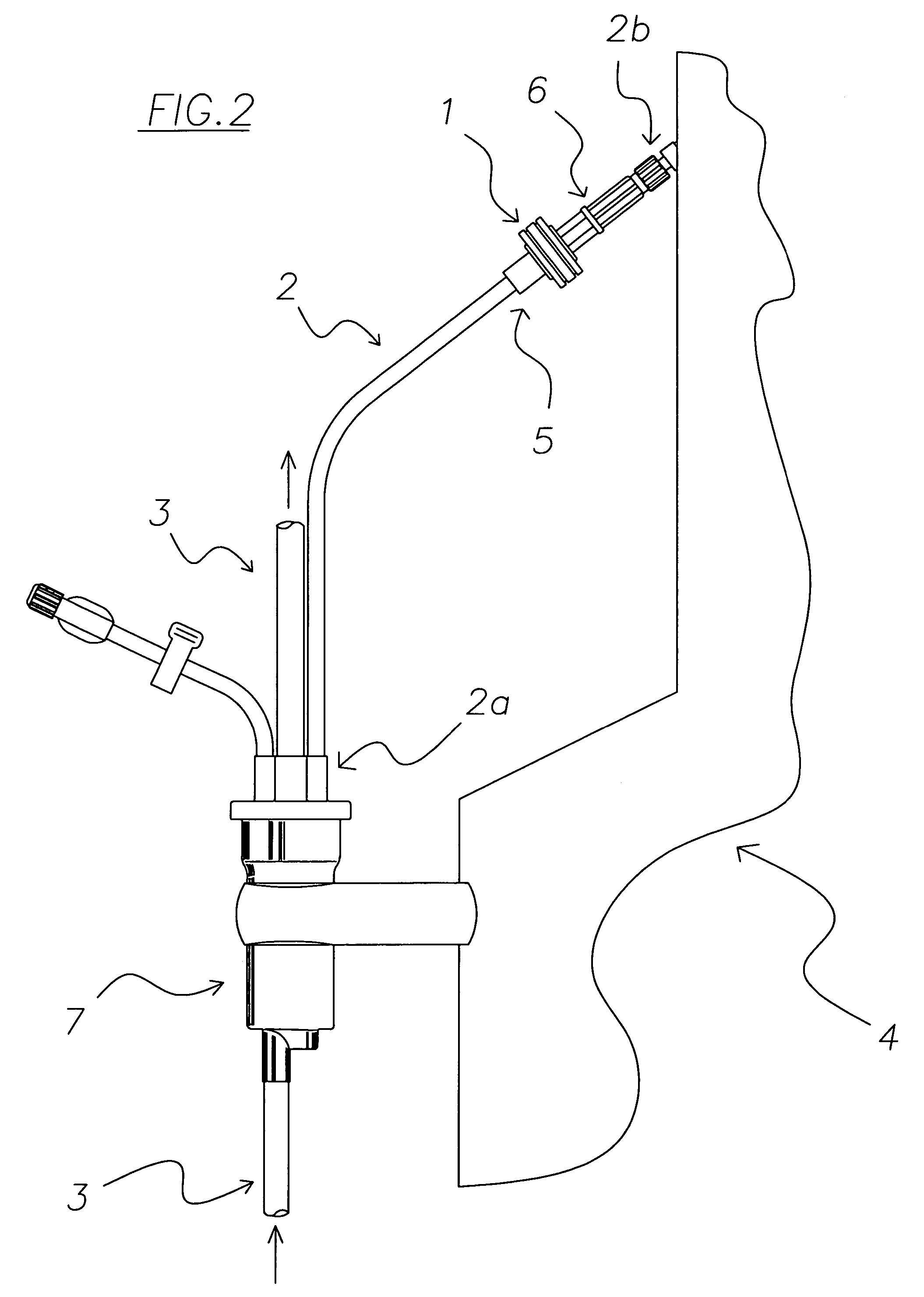
[0042]1 denotes in its entirety a device for protecting medical apparatus from contamination by infectious agents. The protection device 1 is used in particular in combination with apparatus for extracorporeal blood treatment, for example in treatment of renal insufficiency (dialysis machines).

[0043]The device 1 is predisposed to operate along an auxiliary line 2 which connects an extracorporeal blood circuit 3 with a medical apparatus 4. The device 1 has the double function of protecting and transducing, i.e. of protecting the medical apparatus 4, the operators and the surrounding environment, while at the same time transmitting the extracorporeal circuit 3 pressure to a pressure gauge, known and not illustrated, which is part of the medical apparatus 4, with no significant loss of head.

[0044]The device 1 comprises a hollow body having an inlet 5 communicating with the extracorporeal blood circuit 3, and an outlet 6, communicating with the medical apparatus 4. The auxiliary line 2,...


PUM

PropertyMeasurementUnit
plasticaaaaaaaaaa
perimeteraaaaaaaaaa
sizeaaaaaaaaaa

Abstract

A device for protecting medical apparatus from contamination by infectious agents comprises a containment body having an inlet destined to be set in fluid communication with an extracorporeal circuit of blood, and an outlet destined to be connected to a fluid line operatively connected to a pressure gauge of a medical apparatus. The inlet is in gas communication with the outlet across an internal cavity of the containment body. Two hydrophobic membranes are predisposed in the containment body between the inlet and the outlet. The membranes each define an anticontamination barrier which is gas-permeable. The device transmits the pressure of the extracorporeal circuit to the pressure gauge, with no relevant loss of head, while at the same time protecting, with a high degree of security, the medical apparatus from risks of contamination by pathogens originating in the extracorporeal circuit.

Description

CROSS REFERENCE TO RELATED APPLICATIONS[0001]This application claims the priority of Italian Application No. MO2003 A 000079, filed Mar. 21, 2003, and claims the benefit of U.S. Provisional Application No. 60 / 480,403, filed Jun. 23, 2003.BACKGROUND OF THE INVENTION[0002]The invention relates to a device for protecting medical apparatus, in particular from contamination by infectious agents.[0003]Specifically, though not exclusively, the invention can be usefully applied to an apparatus for extracorporeal blood treatment, in particular for treatment of renal insufficiency.[0004]In particular, the invention relates to a transduction-protection device comprising a containing hollow body, having an inlet for communication with an extracorporeal circuit, and an outlet for communication with an operator unit of the medical apparatus, for example with a device for measuring the pressure in the extracorporeal circuit. The device of the operation functions as a transducer, which is both able...

Claims


Application Information

Patent Timeline
Patent Type & Authority Patents(United States)
IPC IPC(8): B01D53/22A61M1/36B01D19/00
CPCA61M1/3639A61M1/3641B01D19/0031A61M2205/16A61M2205/7536A61M2205/7527
Inventor NERI, ROBERTO
Owner GAMBRO LUNDIA AB
Learn More