Spiral linear motor

a linear motor and spiral technology, applied in the direction of mechanical energy handling, electrical equipment, dynamo-electric machines, etc., can solve the problems of large device, complex device, complex device, etc., and achieve the effects of large drive force, small size and light weight, and high accuracy

Inactive Publication Date: 2007-02-13
YOKOHAMA TLO
View PDF12 Cites 6 Cited by
  • Summary
  • Abstract
  • Description
  • Claims
  • Application Information

AI Technical Summary

Benefits of technology

[0009]The present invention constitutes a linear motor that is simultaneously provided with a small size and light weight, high accuracy and a large drive force by integrating a screw mechanism that converts rotational motion to translational motion with an electromagnetic-force power mechanism.
[0010]The present invention removes the effect of friction by rendering the screw mechanism a contactless electromagnetic-force screw mechanism, whereby highly accurate alignment control is possible. Further, because the area of the screw mechanism part exerting the electromagnetic force can be increased, the magnetic flux can be utilized effectively and a drive force that is larger than that of a conventional linear motor of the same volume and same weight can be obtained.
[0012]Further, by reducing the pitch of the rotator and stator, the motor can be rendered a high-rotation-type motor and afforded a small size and light weight.
[0013]Furthermore, because there is no contact between the rotator and stator, the effect of friction is reduced and highly precise alignment is possible.

Problems solved by technology

In cases where a large drive force is obtained by reducing the output of the motor by means of gears, there is a problem that a coulomb frictional force as a result of the gears has a great effect on the alignment accuracy and, in cases where a large drive force is obtained by means of the direct drive system, there is the problem that the device then becomes large.
However, in addition to the problem of alignment accuracy, a constitution that combines a rotational motor and ball screw is confronted by the problem that the device then becomes complex.
A conventional motor constitution is confronted by the problem that the device becomes complex in order to obtain a large drive force.
There is therefore the problem that it is difficult to obtain a large drive force.
Therefore, conventionally, in the case of a constitution that is known as a motor that produces a rectilinear drive force, there is the problem that it is not possible to simultaneously provide the motor with a small size and light weight, high accuracy and a large drive force.

Method used


Image

  • Spiral linear motor
  • Spiral linear motor
  • Spiral linear motor

Examples


Embodiment Construction

[0040]An embodiment of the present invention will be described in detail hereinbelow with reference to the drawings.

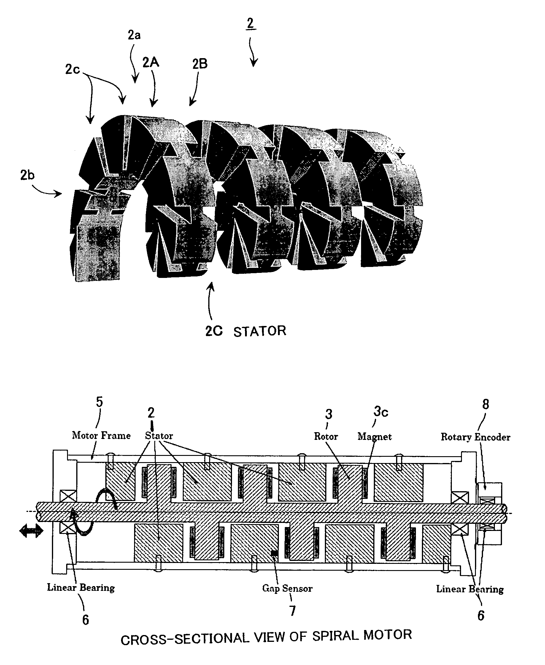
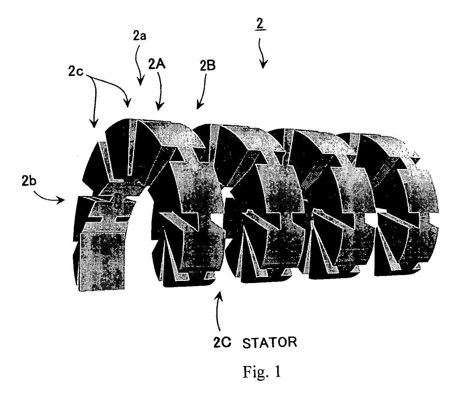
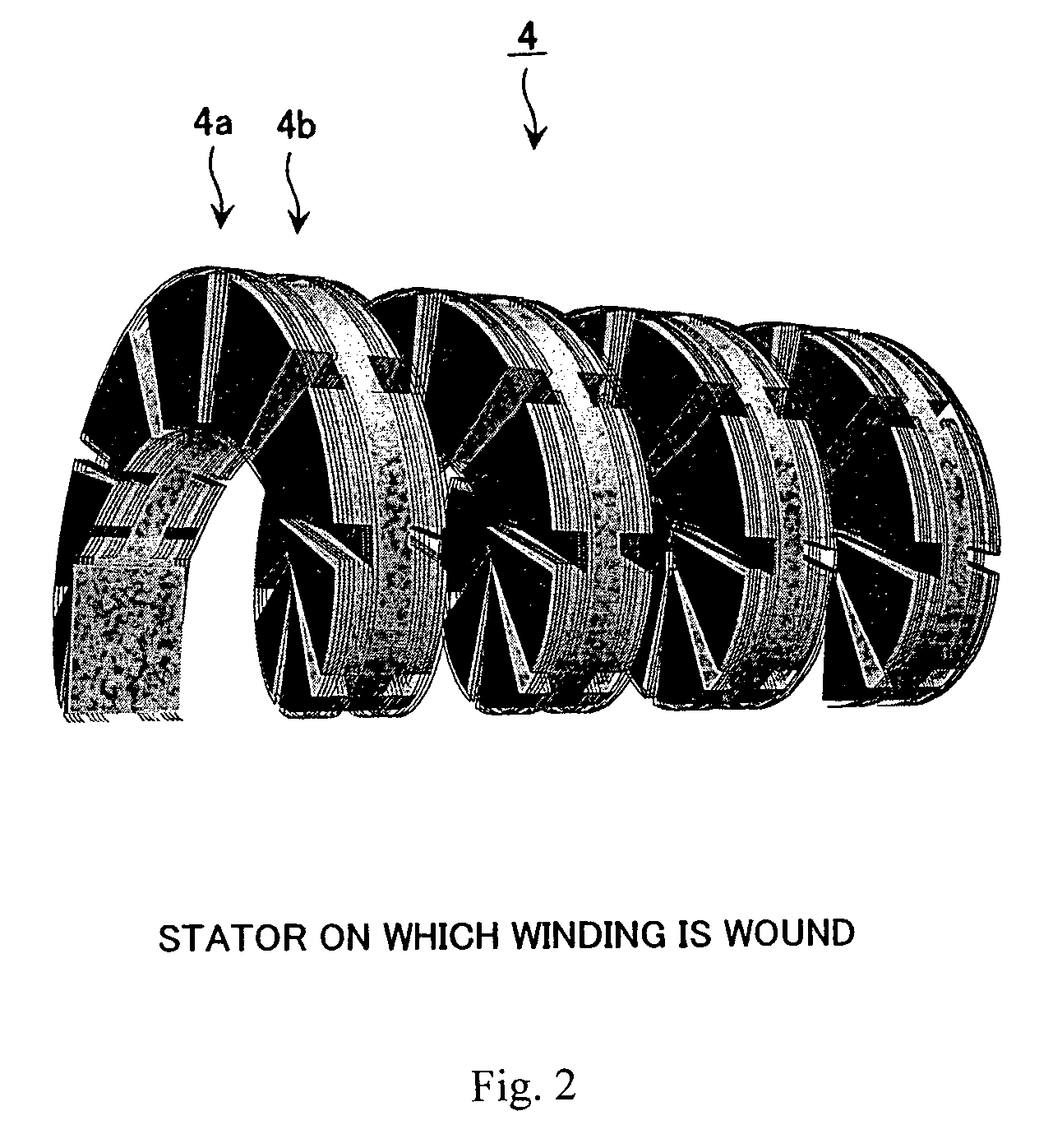
[0041]The stator of the spiral linear motor of the present invention will be described by using FIGS. 1 to 4, the rotator of the spiral linear motor of the present invention will be described by using FIGS. 5 to 7, and each structure of a combination of rotator and stator of the spiral linear motor of the present invention will be described by using FIGS. 8 to 10. Further, the principles of the production of the drive force of the spiral linear motor of the present invention will be described by using FIGS. 11 to 15, the armature circuit of the spiral linear motor of the present invention will be described by using FIG. 16, and the control of the spiral linear motor of the present invention will be described by using FIGS. 17 to 22.

[0042]The spiral linear motor 1 of the present invention comprises a stator 2 and rotator 3 and the rotator 3 moves linearly in an axial di...


PUM


Abstract

A motor producing a rectilinear drive force can be simultaneously provided with a small size and a lightweight, high accuracy and a large drive force.In a spiral linear motor 1, a rotator 3 and stator 2 are both constituted having a spiral shape and, by joining together both spiral-shaped parts, a drive force is produced in the axial direction during rotation in a spiral shape. By affording the spiral linear motor a spiral shape, a large drive force can be obtained similarly to that of a reduction gear and a large drive force can be obtained by utilizing a large area that lies opposite in the axial direction of the rotator and stator.

Description

TECHNICAL FIELD[0001]The present invention relates to a spiral linear motor in which a rotator moves linearly in an axial direction with respect to a stator.BACKGROUND ART[0002]In cases where precise alignment is performed while receiving an external force in the case of an NC mechanism or the like, a large drive force and high rigidity are required. In order to obtain this large drive force, a method for reducing the output of the motor by means of gears and a direct drive system utilizing a large magnetic field are known.[0003]In cases where a large drive force is obtained by reducing the output of the motor by means of gears, there is a problem that a coulomb frictional force as a result of the gears has a great effect on the alignment accuracy and, in cases where a large drive force is obtained by means of the direct drive system, there is the problem that the device then becomes large.[0004]In the case of a linear actuator in particular, a constitution that combines a rotationa...

Claims


Application Information

Patent Timeline
Patent Type & Authority Patents(United States)
IPC IPC(8): H02K41/06H02K1/00H02K41/03
CPCH02K41/031H02K2201/18H02K1/185H02K1/2706
Inventor FUJIMOTO, YASUTAKA
Owner YOKOHAMA TLO
Why Eureka
Try Eureka