Supercharge Your Innovation With Domain-Expert AI Agents!

Overlay process of images

a technology of overlaying and images, applied in the field of projection display, can solve the problem of not being able to overlay an embellishment effect image on the original image,

Inactive Publication Date: 2007-02-13
SEIKO EPSON CORP
View PDF36 Cites 7 Cited by
  • Summary
  • Abstract
  • Description
  • Claims
  • Application Information

AI Technical Summary

Benefits of technology

The present invention provides a technology for overlaid projection display apparatuses that can embellish images without relying on the capabilities of the image supply apparatus. The apparatus includes an embellishment effect memory for storing embellishment effect images, an image embellishment section for generating embellished image data, and a light modulation unit for projecting the embellished image onto a screen. The apparatus can also include a frame memory for storing the original image data and a synthesizer section for synthesizing the embellishment effect image with the original image data. The embellishment effect images can be overlaid on the original image by selecting the appropriate embellishment effect image and writing it to the frame memory. The degree of transparency of the embellishment effects can be adjusted by changing the coefficients in the multiplier section.

Problems solved by technology

Moreover, when signals given to the projection display apparatus are image signals output from a video recorder or television, it has not been possible to overlay an embellishment effect image on the original image.
That is, a problem has been that whether or not an embellishment effect can be imparted to a projected image has depended on the capabilities of the image supply apparatus that supplies an image to the projection display apparatus.

Method used


Image

  • Overlay process of images
  • Overlay process of images
  • Overlay process of images

Examples


first embodiment

A. First Embodiment

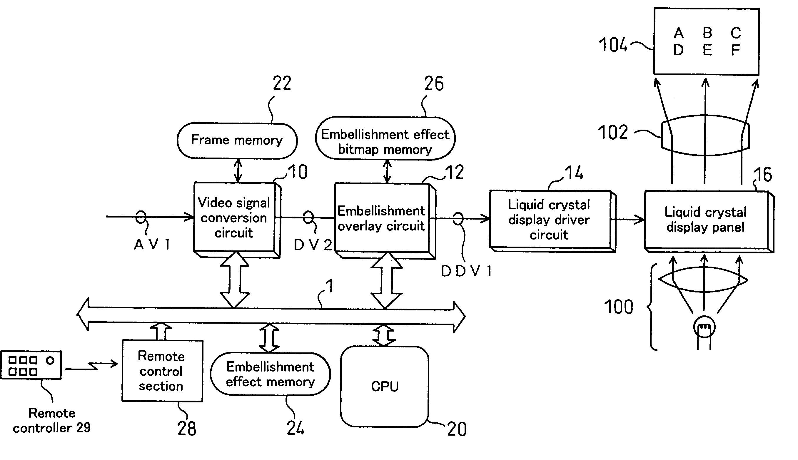
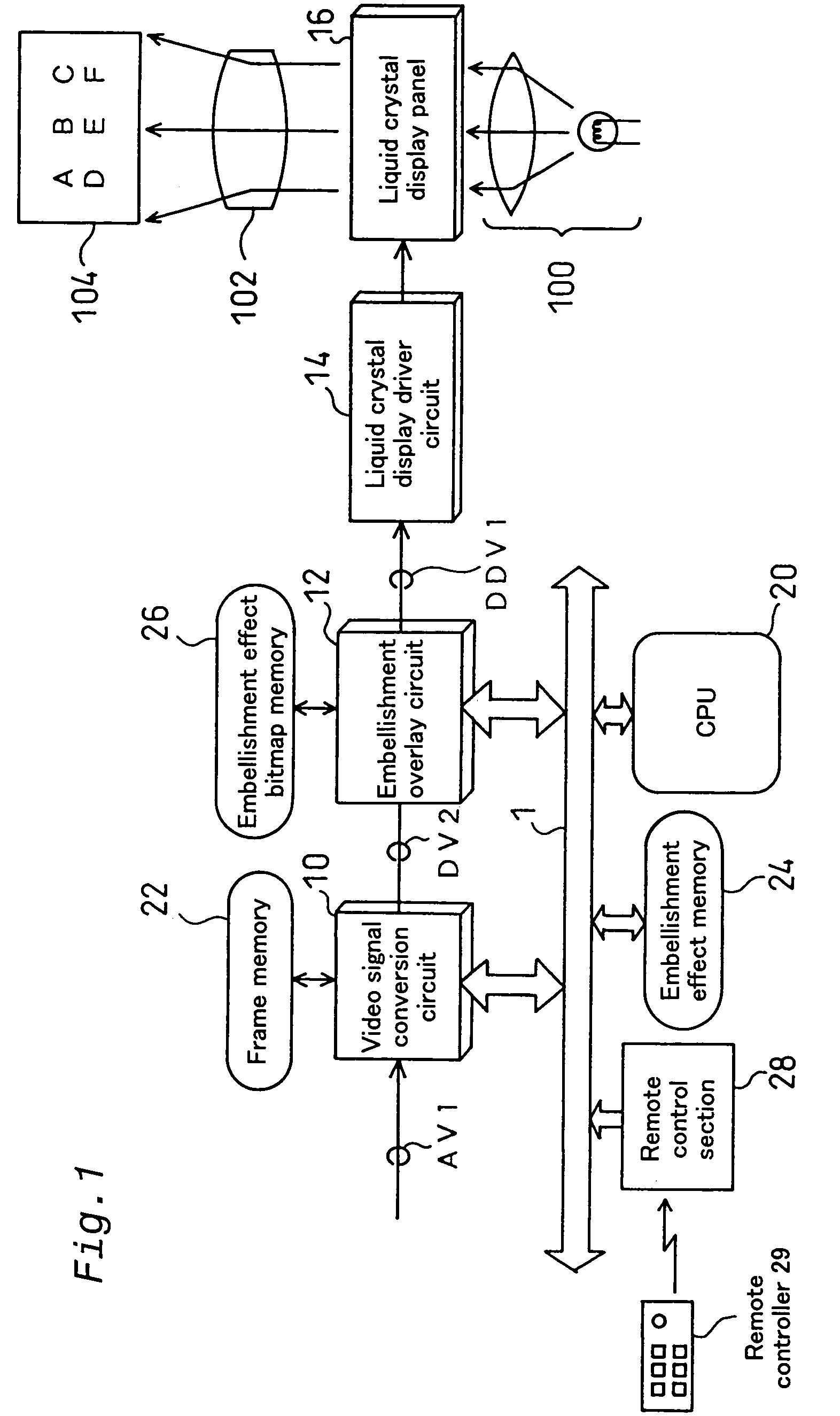
[0088]Modes of carrying out the invention will now be explained with reference to embodiments. FIG. 1 is a block diagram for schematically illustrating the general configuration of a projection display apparatus that is a first embodiment of this invention. The projection display apparatus includes a video signal conversion circuit 10, an embellishment overlay circuit 12, a liquid crystal display driver circuit 14, a liquid crystal display panel 16, a frame memory 22, an embellishment effect memory 24, an embellishment effect bitmap memory 26, a remote control section 28, a CPU 20, an illumination optical system 100 and a projection optical system 102. The video signal conversion circuit 10, embellishment overlay circuit 12, embellishment effect memory 24, remote control section 28 and CPU 20 are connected to each other via a bus 1. The liquid crystal display driver circuit 14 is also connected to the bus 1, but this is not shown in FIG. 1. The liquid crystal disp...

second embodiment

B. Second Embodiment

[0133]FIG. 12 is a block diagram for schematically illustrating the general configuration of a projection display apparatus that is a second embodiment of this invention. The projection display apparatus includes a video signal conversion circuit 60, a liquid crystal display driver circuit 14, a liquid crystal display panel 16, a frame memory 22, an embellishment effect memory 24, a remote control section 28, a CPU 20, an illumination optical system 100 and a projection optical system 102. The video signal conversion circuit 60, embellishment effect memory 24, remote control section 28 and CPU 20 are connected to each other via a bus 1. The liquid crystal display driver circuit 14 is also connected to the bus 1, but the connection is not shown in FIG. 12.

[0134]The projection display apparatus of this second embodiment does not have the embellishment overlay circuit 12 or the embellishment effect bitmap memory 26 possessed by the first embodiment (FIG. 1). The vid...

third embodiment

C. Third Embodiment

C-1. Configuration and Operation of the Projection Display Apparatus:

[0148]FIG. 15 is a block diagram for schematically illustrating the general configuration of a projection display apparatus that is a third embodiment of this invention. The projection display apparatus includes a video signal conversion circuit 210, an embellishment overlay circuit 212, a liquid crystal light valve driver circuit 214, a liquid crystal light valve 216, a frame memory 222, an embellishment image storage memory 224, an embellishment image expansion memory 226, an embellishment image drawing memory 227, a remote control section 28, a CPU 20, an illumination optical system 100 and a projection optical system 102. The video signal conversion circuit 210, embellishment overlay circuit 212, embellishment image storage memory 224, remote control section 28 and CPU 20 are connected to each other via a bus 1. The embellishment image expansion memory 226 and embellishment image drawing memo...


PUM


Abstract

The present invention provides a technology that enables projection images to be overlaid with embellishment effects without depending on the capabilities of the image supply apparatus. A projection display apparatus that projects images onto a screen responsive to given image data, comprises: an embellishment effect memory for storing embellishment effect data representing an embellishment effect image that can be used to embellish an arbitrary image; an image embellishment section that generates embellished image data by overlaying an original image represented by the given image data and the embellishment effect image; a light modulation unit that is driven responsive to the embellished image data pixel by pixel; and an optical system for projecting onto the screen the embellished image obtained by the light modulation unit. A projection display apparatus superimposes the embellishment effect on the projected image without having to rely on the capabilities of an image supply apparatus.

Description

[0001]This application is a Continuation of international PCT application PCT / JP99 / 00434, filed on Aug. 16, 1999, pending.BACKGROUND OF THE INVENTION[0002]1. Field of the Invention[0003]The present invention relates to an image display apparatus, particularly to a projection display apparatus technology that project images onto a screen based on given image data.[0004]2. Description of the Background[0005]The ability of projection display apparatuses to display enlarged given images on a projection screen has led to their extensive use in presentations. In a presentation an explanation is provided based on projected images, so it is convenient to be able to overlay the images with an embellishment effect image (embellishment image) such as an arrow graphic or the like to indicate specific locations on the projected image.[0006]In prior art projection display apparatuses, when, for example, an embellishment effect image is overlaid on an original image given from a personal computer,...

Claims


Application Information

Patent Timeline
Patent Type & Authority Patents(United States)
IPC IPC(8): G09G5/00G09G3/00G09G3/36H04N5/445H04N5/74
CPCG09G3/36G09G5/003H04N5/44504G09G3/001H04N5/7441G09G2340/10G09G2340/125G09G5/397H04N5/74
Inventor ITOH, TAKAFUMIAKAIWA, SHOICHIMIYASHITA, KIYOSHI
Owner SEIKO EPSON CORP
Features
  • R&D
  • Intellectual Property
  • Life Sciences
  • Materials
  • Tech Scout
  • Unparalleled Data Quality
  • Higher Quality Content
  • 60% Fewer Hallucinations
Learn More