Removable control panel for multi-function equipment

Active Publication Date: 2007-02-13
XEROX CORP
View PDF68 Cites 35 Cited by
  • Summary
  • Abstract
  • Description
  • Claims
  • Application Information

AI Technical Summary

Benefits of technology

[0007]What is disclosed are various embodiments of a removable control panel for multi-function equipment for the alternative navigation and selection of various available options presented. The embodiment of FIG. 7 is shown comprising four arrow-shaped buttons so the impaired user can navigate controls and options displayed. An ENTER button is provided for formalizing the entry of desired selections, where required. An UNDO button is provided to de-select entries. A STATUS button initiates audio, visual, or tactile feedback as to machine state, status, and other assistance. An ENLARGE button is provided by which a

Problems solved by technology

Such displays often have many levels of hierarchically structured menus because, depending on the complexity of the number and type of selectable options there may not be enough real estate or physical room on the display on which to fit all the various options available.
Individuals that are impaired may encounter difficulty setting up, configuring or operating such multi-function equipment.
If, for example, the user is visually impaired they may not clearly see the options displayed or other helpful information.
If the user is completely visually impaired they may not be able to use such multi-function equipment without the assistance of others.
If the user has limited motor skills or has difficulty with fine motor control their use of such equipment may be precluded because they may not be able to manipulate the controls or keypad buttons to navigate and select options presented or, if the machine has a touch screen display which requires an accurate p

Method used


Image

  • Removable control panel for multi-function equipment
  • Removable control panel for multi-function equipment
  • Removable control panel for multi-function equipment

Examples


Embodiment Construction

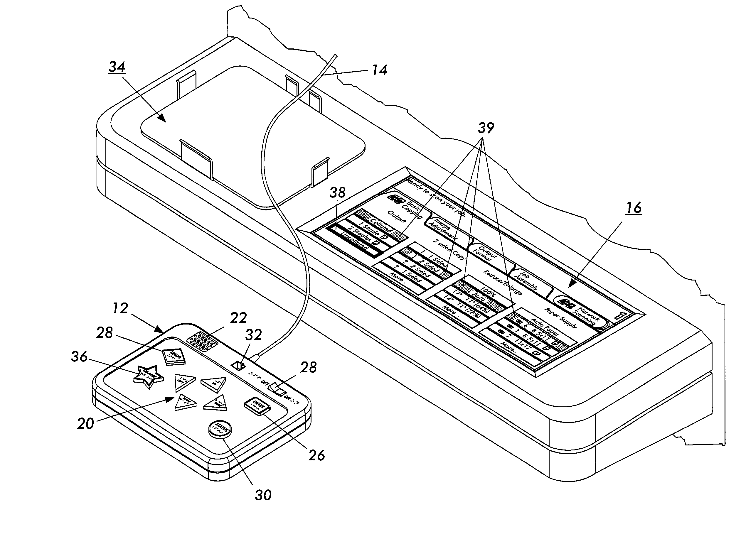
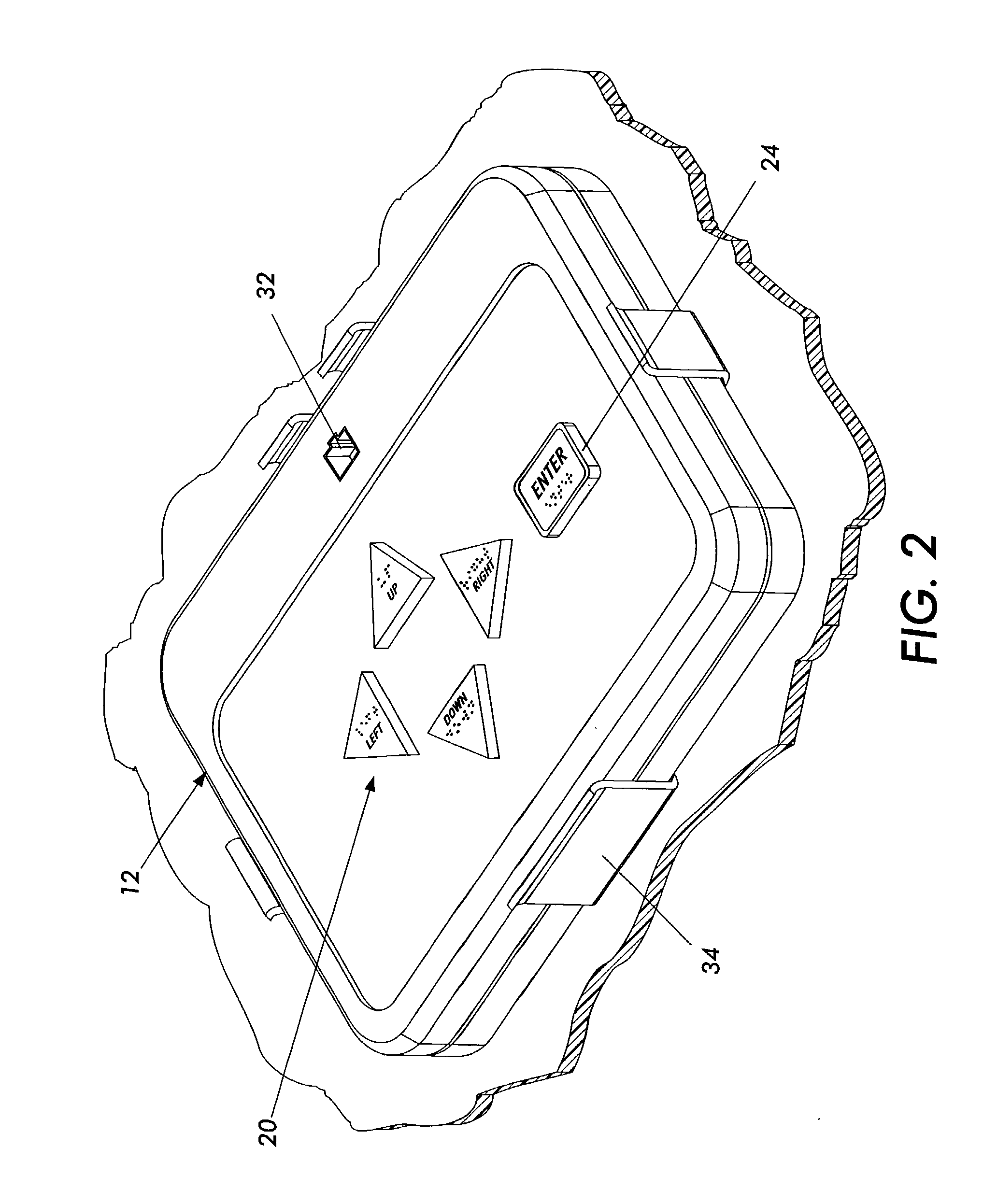
[0020]What is disclosed are various embodiments of a removable control panel for multi-function equipment for the alternative and selection of various available options presented.

[0021]It should be understood that depending on the type and complexity of the office machine or other such multi-function equipment to which the present invention finds its intended uses, inter-activity between software and hardware mechanisms would necessarily differ as a matter of design as would the type options available thereon. As such, the disclosure herein is necessarily limited to detailing how the features of the present invention perform and what they are intended to do in terms of solving the problem in the arts previously discussed. The user's selection of controls or options presented in turn initiate machine responses and / or present to the user the next option state whether it be other selectable features or the presentation of additional levels of more selectable options. Those skilled in t...


PUM


Abstract

What is disclosed are various embodiments of a removable control panel for multi-function equipment for the alternative navigation and selection of various available options presented. The embodiment of FIG. 7 is shown comprising four arrow-shaped buttons so the impaired user can navigate controls and options displayed. An ENTER button is provided for formalizing the entry of desired selections, where required. An UNDO button is provided to de-select entries. A STATUS button initiates audio, visual, or tactile feedback as to machine state, status, and other assistance. An ENLARGE button is provided by which a visually impaired user can enlarge their current focus for easier seeing and reading. An ON/OFF switch enables/disables feedback for use in those work environments where such assistance is not desired. Each of the buttons has an identifying shape, which can be differentiated by feel, and Braille and other text are additionally provided. This particular embodiment further advantageously comprises an interface jack for use by those users who make use of communicative devices. The present device is removable from an accessible holding carriage for use by persons working from either a wheelchair or from a prone position.

Description

CROSS-REFERENCE TO RELATED APPLICATIONS[0001]Reference is made to commonly-assigned copending U.S. patent application Ser. No. 10 / 243,570, filed herewith, entitled “EMBEDDED CONTROL PANEL FOR MULTI-FUNCTION EQUIPMENT”, by Debora Margaret Hejza Litwiller; U.S. patent application Ser. No. 10 / 179,555, filed Jun. 24, 2002, entitled “SYSTEM AND METHOD FOR AUDIBLE FEEDBACK FOR TOUCH SCREEN DISPLAYS”, by Debora Margaret Hejza Litwiller; and U.S. patent application Ser. No. 10 / 179,530, filed Jun. 24, 2002, entitled “SYSTEM FOR AUDIBLE FEEDBACK FOR TOUCH SCREEN DISPLAYS”, by Debora Margaret Hejza Litwiller, the disclosures of which are incorporated herein.FIELD OF THE INVENTION[0002]The present invention is generally directed to control panels of multi-function office equipment and, in particular, to control panels which enable impaired users thereof to navigate the controls of said equipment and to navigate and select various options displayed or otherwise presented.BACKGROUND OF THE INVENT...

Claims


Application Information

Patent Timeline
IPC IPC(8): G09G5/00G06F3/00G06F3/01G06F3/02G06F3/033
CPCG06F3/011G06F3/033G06F3/0202
Inventor LITWILLER, DEBORA MARGARET HEJZA
Owner XEROX CORP
Why Eureka
Try Eureka