Simplified message-passing decoder for low-density parity-check codes

a message-passing decoder and low-density parity-checking technology, applied in the field of channel code decoding, can solve the problems of increasing the area cost of the integrated circuit, raising the implementation cost, and affecting the implementation of nonlinear functions, so as to reduce approximation errors

Inactive Publication Date: 2007-02-13
ELECTRONICS & TELECOMM RES INST
View PDF8 Cites 91 Cited by
  • Summary
  • Abstract
  • Description
  • Claims
  • Application Information

AI Technical Summary

Benefits of technology

[0008]It is an advantage of the present invention to implement calculation of a parity-check message in a decoder for LDPC codes by applying a linear approximation method to individual intervals divided from an input interval without using a read-only memory (ROM). The parity-check function used for the calculation of the parity-check message is a monotonically decreasing function that shows a similar decreasing tendency to an exponential function, so the interval can be determined in the manner of the exponential function to drastically reduce approximation errors caused by linear approximation. For the linear approximation, the slope for each interval and the function value at the interval boundary are necessary. A simple multiplier is constructed with a combination of summators and shifters. Accordingly, the entire parity-check function can be calculated only with the operations of summators and shifters. The present invention proposes a decoder that implements the parity-check function in a simply way.

Problems solved by technology

This LLR message decoding method involves a logarithm function operation in message calculation, and it causes a problem in regard to implementation of a nonlinear function.
The use of this method requires memories of a large capacity and increases the area cost of the integrated circuit, thereby raising the cost of implementation.
But, reducing the number of bits representing input and output deteriorates the accuracy of the message calculation to reduce the entire decoding performance and increase the BER.

Method used


Image

  • Simplified message-passing decoder for low-density parity-check codes
  • Simplified message-passing decoder for low-density parity-check codes
  • Simplified message-passing decoder for low-density parity-check codes

Examples


Embodiment Construction

[0019]In the following detailed description, only the preferred embodiment of the invention has been shown and described, simply by way of illustration of the best mode contemplated by the inventor(s) of carrying out the invention. As will be realized, the invention is capable of modification in various obvious respects, all without departing from the invention. Accordingly, the drawings and description are to be regarded as illustrative in nature, and not restrictive.

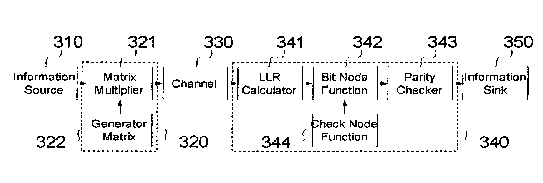
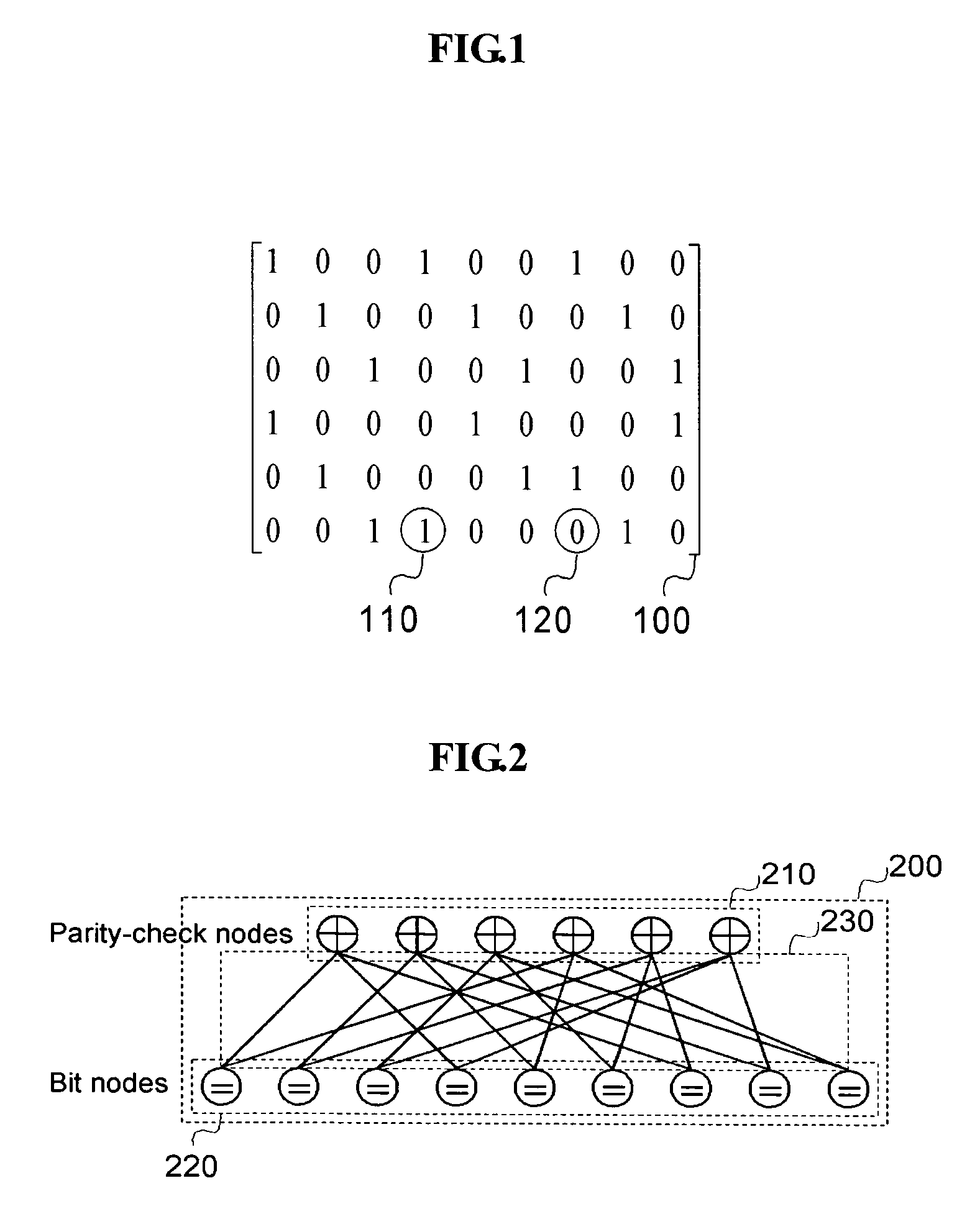
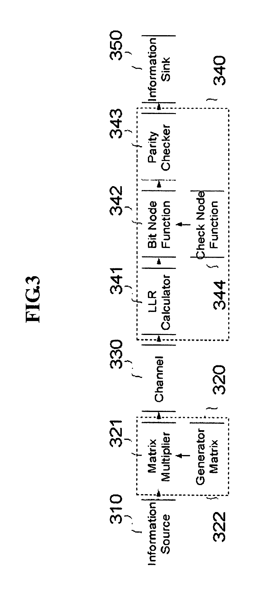
[0020]The present invention can be applied to decoding of block codes encoded using LDPC codes. The block codes are encoded by way of a sparse parity-check matrix 100 designed to have the least number of elements 110 other than “0”120, and a related generator matrix. The coding method is exactly the same as the coding of general block codes.

[0021]In the decoding method of LDPC codes, a Tanner graph 220 is defined from the sparse parity-check matrix 100, and the message-passing algorithm is applied to the corresponding ...


PUM


Abstract

Disclosed is an implementation method for simplifying a complicated message-passing function in a decoder for decoding block codes encoded with low-density parity-check (LDPC) codes and only using a summator and a shifter to simplify the hardware structure of the decoder, in which method the input interval of the message-passing function for binary representation of a message input is divided and the respective divided intervals are linearized to allow the calculation of the output of the message-passing function without using a memory. Based on the fact that the message-passing function is similar in structure to an exponential function, the linearized intervals are set to make the maximum value expressible in each digit of the binary representation as the boundary of the intervals.

Description

CROSS REFERENCE TO RELATED APPLICATION[0001]This application claims priority to and the benefit of Korea Patent Application No. 2002-83721 filed on Dec. 24, 2002 in the Korean Intellectual Property Office, the content of which is incorporated herein by reference.BACKGROUND OF THE INVENTION[0002](a) Field of the Invention[0003]The present invention relates to a decoding technology for channel codes. More particularly, the present invention relates to a message-passing decoder for LDPC (Low-Density Parity-Check) codes that receives data encoded with LDPC codes on a channel, having a consecutive output values, and decodes the coded data using a message-passing decoding algorithm.[0004](b) Description of the Related Art[0005]LDPC codes are linear block codes reported by Gallager in 1962, and they are defined as a sparse parity-check matrix of which the elements are mostly “0”. LDPC codes were out of the public's mind for a long time due to expense of implementation, but they were re-dis...

Claims


Application Information

Patent Timeline
Patent Type & Authority Patents(United States)
IPC IPC(8): H03M13/00H03M13/11H04L1/00
CPCH03M13/1117H04L1/0057H04L1/0045H03M13/11
Inventor LEE, SANG-HYUNKIM, YUN-HEEKIM, KWANG-SOONCHANG, KYUNG-HI
Owner ELECTRONICS & TELECOMM RES INST
Why Eureka
Try Eureka