Information transmission system, information output apparatus, information input apparatus, and connection relationship identification method

Inactive Publication Date: 2007-02-13
SONY CORP
View PDF5 Cites 24 Cited by
  • Summary
  • Abstract
  • Description
  • Claims
  • Application Information

AI Technical Summary

Benefits of technology

[0082]In this configuration, an analog connection relationship between the information output appar

Problems solved by technology

Further, when the information input apparatus having a plurality of analog input terminals is to be supplied with an analog signal from a target electronic

Method used


Image

  • Information transmission system, information output apparatus, information input apparatus, and connection relationship identification method
  • Information transmission system, information output apparatus, information input apparatus, and connection relationship identification method
  • Information transmission system, information output apparatus, information input apparatus, and connection relationship identification method

Examples


embodiment 1

[0098][Outline and Connection Relationships of Home Network System]

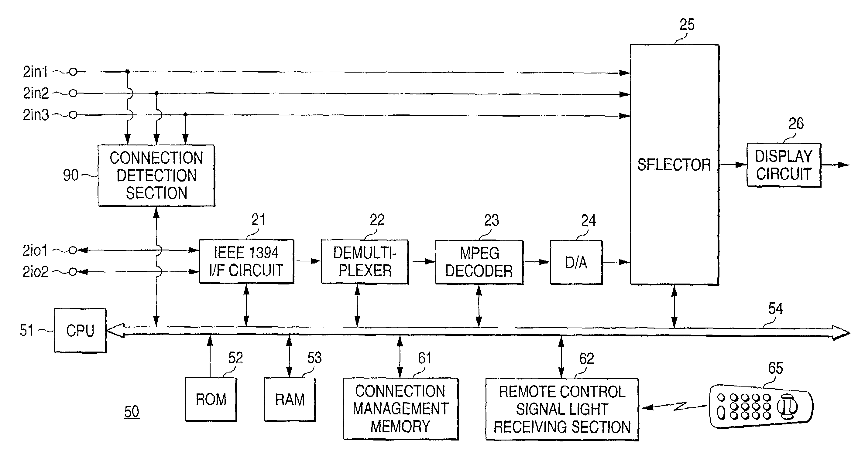
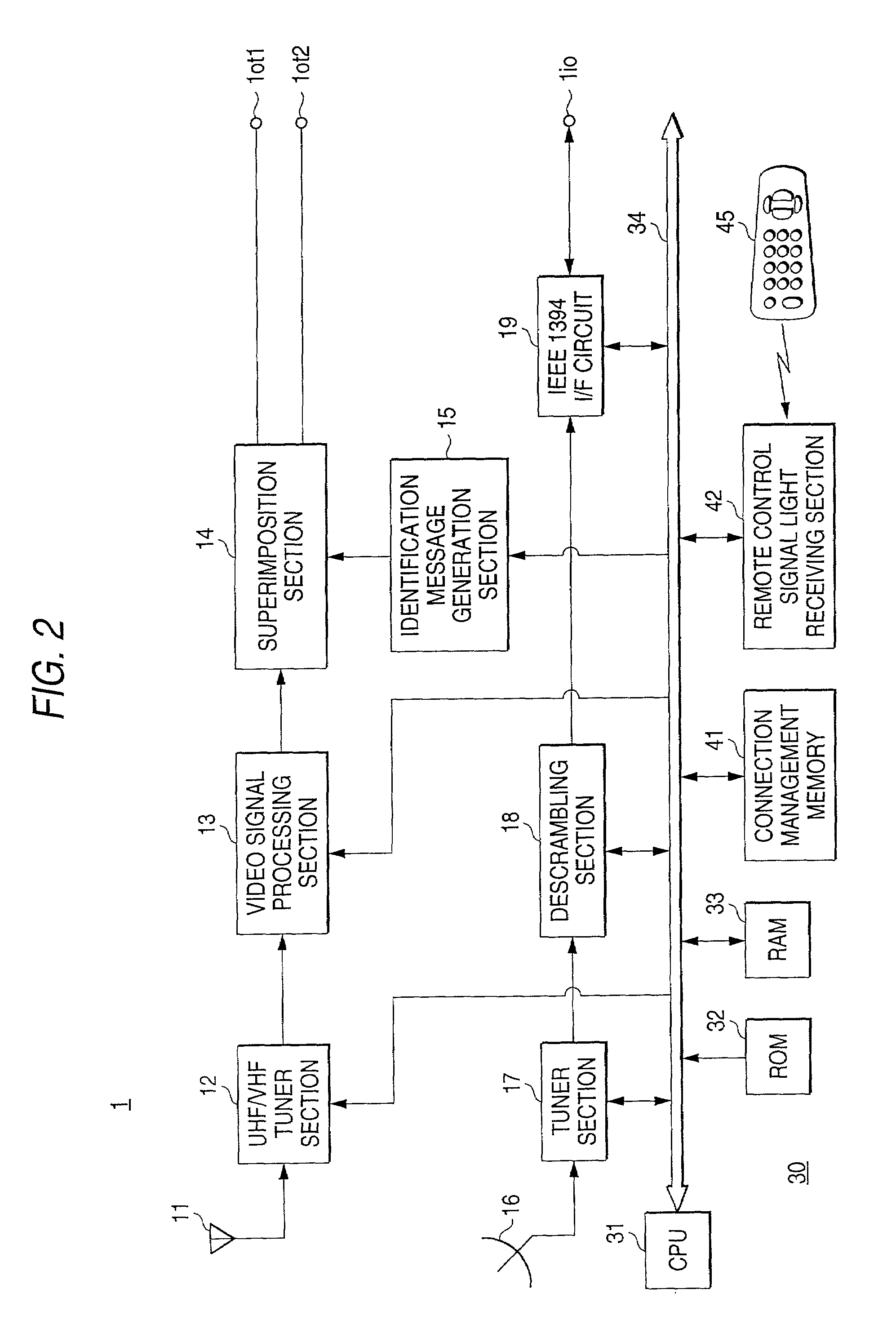
[0099]FIG. 2 is a block diagram of an IRD 1 according to a first embodiment to which the information output apparatus according to the invention is applied. FIG. 3 is a block diagram of a monitor receiver 2 according to the first embodiment to which the information input apparatus according to the invention is applied.

[0100]In the first embodiment, a home network system according to the invention is realized by using the IRD 1 and the monitor receiver 2 that are shown in FIGS. 2 and 3, respectively, and other apparatuses. Therefore, before describing the details of the individual apparatuses such as the IRD 1 and the monitor receiver 2 that form the home network system, the outline and the connection relationships of the home network system according to the first embodiment will be described first.

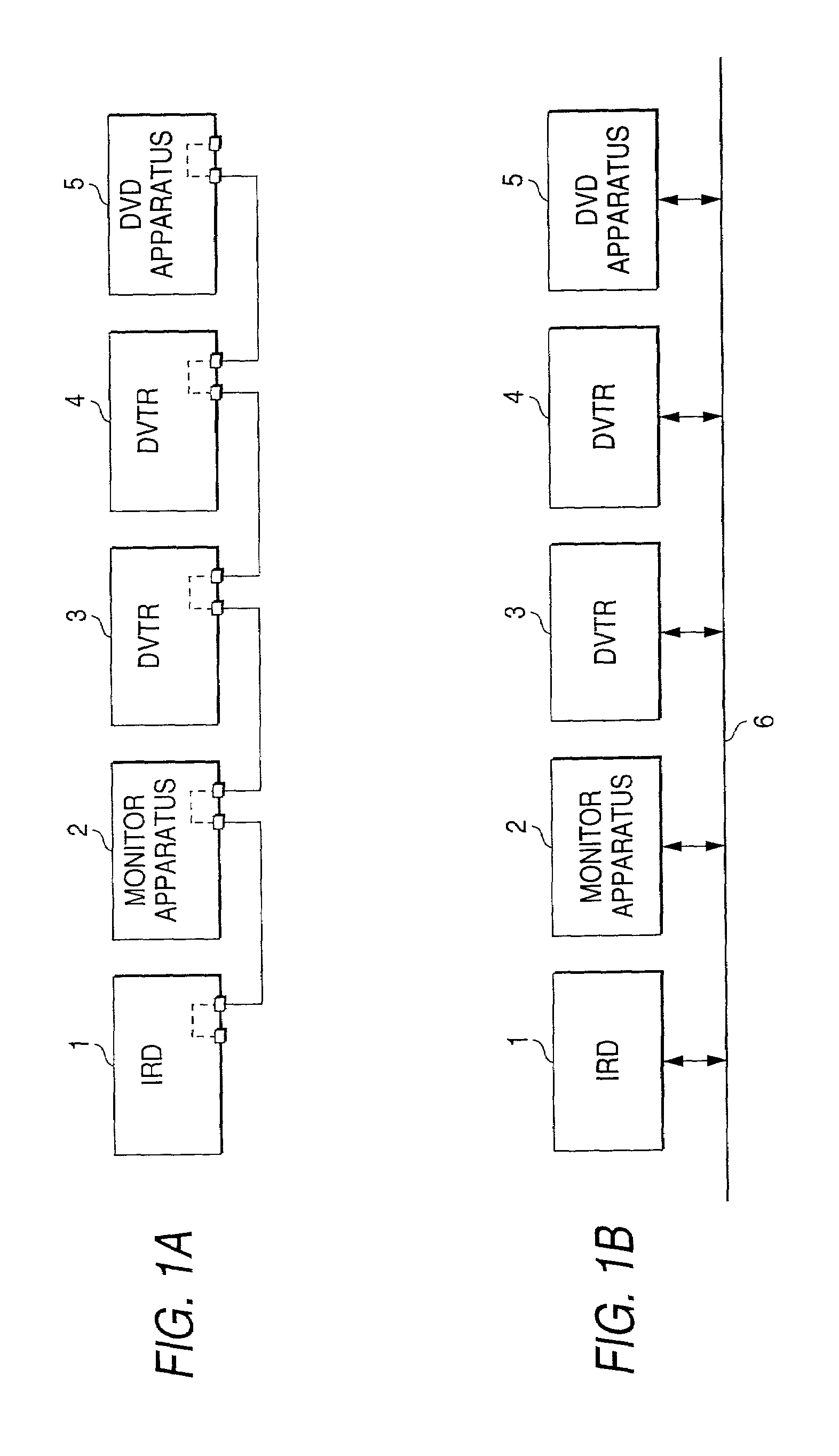
[0101]FIGS. 4 and 5 show an outline and a connection relationship of the home network system according to the first embod...

embodiment 2

[0245]In the above-described first embodiment, an analog input terminal being supplied with an analog signal on which information for identification is superimposed by sending the information for identification as a display message from an analog output terminal of the IRD 1 as an information output apparatus and a user's manually switching among the input terminals of the monitor receiver 2.

[0246]The second embodiment is intended to eliminate a user's manipulations on the monitor receiver in a process for identifying an analog input terminal and to identify an analog input terminal of the monitor receiver automatically. As in the case of the first embodiment that has been described above with reference to FIGS. 4-6, the second embodiment will also be described for an example in which a home network is formed by an IRD (information output apparatus), a monitor receiver (information input apparatus), and a VDTR (information output apparatus) and an analog connection relationship betw...


PUM


Abstract

A control section of an IRD sends an identification start request to a digital bus via a digital input/output terminal. The control section generates an identification display message by controlling an identification display message generation section, makes a superimposition section superimpose the identification display message on an analog video signal, and outputs a resulting signal via an analog output terminal. An information input apparatus allows a user to identify an input terminal connected to the output terminal of the IRD among a plurality of input terminals of the self apparatus by reproducing the identification display message and presenting it to the user.

Description

BACKGROUND OF THE INVENTION[0001]1. Field of the Invention[0002]The present invention relates to an information transmission system that is formed by connecting electronic apparatuses by using two kinds of different interfaces, that is, an interface enabling sending and reception of control information such as a digital interface according to the IEEE 1394 standard and an interface enabling transmission of only an information signal such as an analog interface, as well as to an information output apparatus, an information input apparatus, and a connection relationship identification method that are used in such an information transmission system.[0003]2. Description of the Related Art[0004]In recent years, various digital contents have come to be provided abundantly via communication media such as broadcast media and the Internet and via recording media such as the DVD (digital video disc). It is now being considered how to broaden the range of use of digital contents that have come...

Claims


Application Information

Patent Timeline
IPC IPC(8): H04N5/445G06F13/00G06F3/00G06F13/14H04H20/00H04H60/80H04L12/28H04L12/64H04N5/44H04N5/60H04N5/765H04N5/775H04N7/088H04N7/24H04N21/431H04N21/436H04N21/442H04N21/485
CPCH04H60/80H04L12/40117H04L12/6418H04N5/4401H04N5/44513H04N21/485H04N7/088H04N21/4312H04N21/4314H04N21/43615H04N21/44227H04N5/765H04N5/60H04N5/775H04N21/426H04N21/47
Inventor KIMURA, YUJISADANAKA, KAZUEKOBAYASHI, SATOSHIUTSUNOMIYA, HIROSHIKAIBUKI, FUTOSHISUZUKI, KAZUHIROMATSUOKA, KENJISATO, MASAHIKOSATO, MAKOTO
Owner SONY CORP
Why Eureka
Try Eureka