
Determining the pressure of formation fluid in earth formations surrounding a borehole

a technology of formation fluid and pressure, which is applied in the field of oil and gas exploration, can solve the problems of difficult removal, sticking to the borehole, and techniques that are not generally viewed as reliable predictors of actual formation fluid pressure, and achieve the effect of minimizing pressure overshoo

Inactive Publication Date: 2007-02-20
SCHLUMBERGER TECH CORP
View PDF48 Cites 49 Cited by
  • Summary
  • Abstract
  • Description
  • Claims
  • Application Information

AI Technical Summary

Benefits of technology

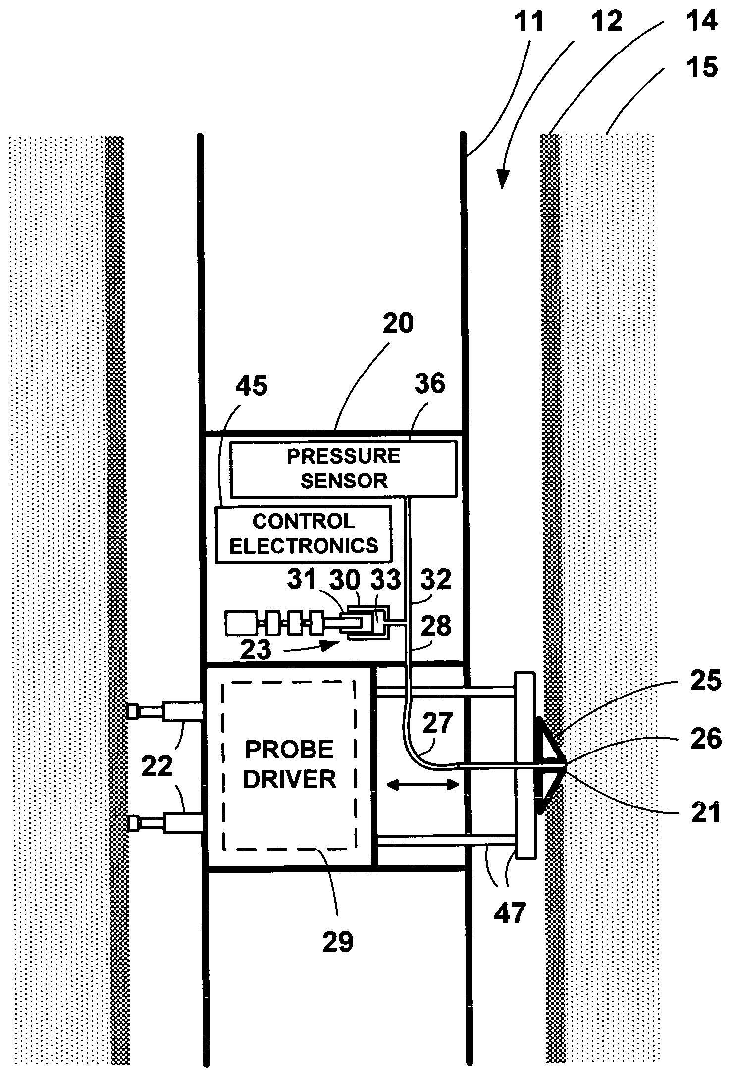
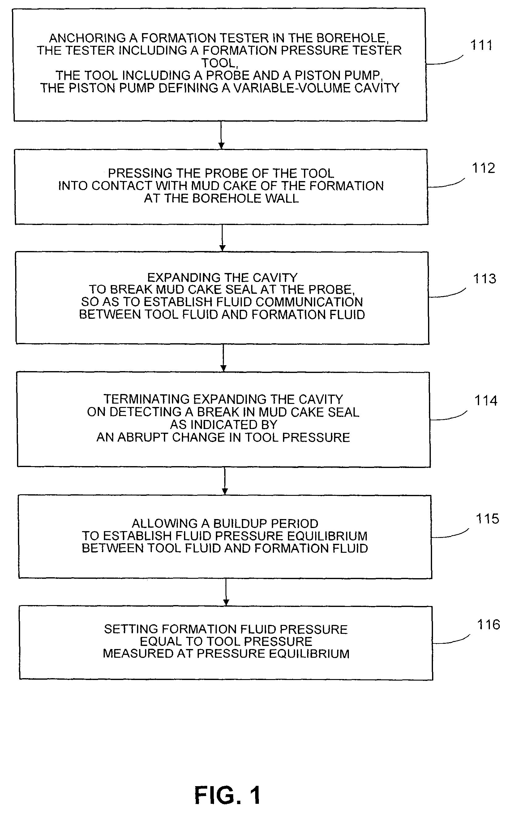
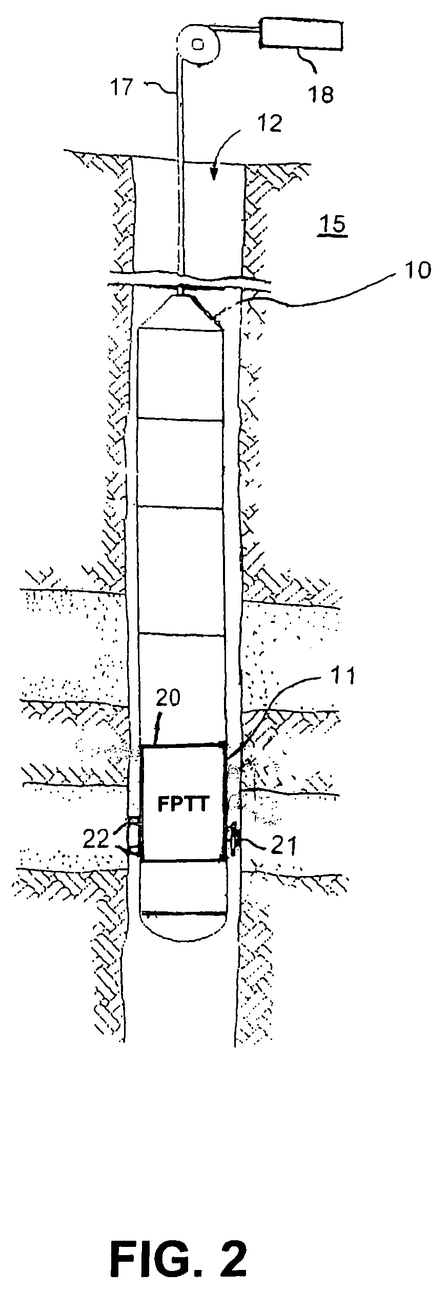
The invention provides a method and apparatus for determining the pressure of formation fluid surrounding a borehole using a downhole probe and a pretest piston pump. The method involves expanding the volume of a cavity in fluid communication with the probe to break a mud cake seal at the probe and allow fluid flow to establish pressure equilibrium between the tool and the formation fluid. The pressure of the formation fluid is then set equal to the tool pressure. The apparatus includes an elongated body with a probe and a pretest piston pump, which is used to expand the cavity and detect the break in the mud cake seal. The invention allows for accurate and efficient determination of formation fluid pressure, which is important for the evaluation of oil and gas reservoirs.

Problems solved by technology

If the formation tester is set at a particular location for too long a time, it could stick in the borehole and become difficult to remove.
However, these techniques are not generally viewed as reliable predictors of actual formation fluid pressure.

Method used


Image

  • Determining the pressure of formation fluid in earth formations surrounding a borehole
  • Determining the pressure of formation fluid in earth formations surrounding a borehole
  • Determining the pressure of formation fluid in earth formations surrounding a borehole

Examples


Embodiment Construction

General

[0027]The invention provides a method and tool for determining the pressure of formation fluid in earth formation surrounding a borehole more quickly and potentially more accurately than methods used in existing wireline formation testers. By determining the pressure more quickly, the invention reduces the risk of the tool sticking in the borehole.

[0028]In particular, the method in a preferred embodiment includes actively terminating the expansion of the volume of the cavity of a pretest chamber during the “draw-down” period of a method similar to the prior art method described above.

[0029]Actively terminating the expansion of the volume of the cavity upon detection of an abrupt change in pressure prevents excessive pressure overshoot. See “overshoot” in FIGS. 5 and 6. “Pressure overshoot” refers to the tool pressure always being less than the formation pressure Pf at the conclusion of drawdown. Withdrawing fluid from the formation into the tool requires that the tool pressur...


PUM


Abstract

A method for determining formation fluid pressure in earth formation surrounding a borehole wall uses a downhole probe coupled to a variable-volume cavity. The probe is driven into contact with formation at the borehole wall. The method includes expanding the volume of the cavity during a first period of time to establish fluid communication between tool fluid and formation fluid, by withdrawing a minimal amount of fluid from the formation. During a second period of time the tool pressure is allowed to equilibrate to formation pressure. When pressure equilibrium is established, formation fluid pressure is set equal to tool pressure. A preferred embodiment includes terminating expanding the volume of the cavity on detecting a break in the mud cake seal. An associated formation pressure tester tool includes an elongated body; a probe defining a formation fluid inflow aperture, an electromechanical assembly defining a variable-volume cavity, a pretest flow line coupling the aperture to the cavity, a pressure sensor coupled to the cavity; and downhole electronic means for controlling the expansion of the volume of the cavity.

Description

[0001]This application is related to co-owned, co-pending U.S. application Ser. No. 10 / 248,535, filed 27 Jan. 2003. It is also related to co-owned, co-pending U.S. application Ser. No. 10 / 237,394, filed 9 Sep. 2002, and to co-owned, co-pending U.S. application Ser. No. 10 / 434,923, filed 9 May 2003, that is a continuation-in-part of U.S. application Ser. No. 10 / 237,394. These previously filed applications are incorporated herein by reference.FIELD OF THE INVENTION[0002]The present invention relates generally to the field of oil and gas exploration. More particularly, the invention relates to methods for determining at least one property of an earth formation surrounding a borehole using a formation tester.BACKGROUND OF THE INVENTION[0003]The term “wireline formation tester” is the generic name in the petroleum industry for a wireline logging tool used for determining formation fluid pressure and other parameters in a reservoir. A prior art wireline formation tester typically includes...

Claims


Application Information

Patent Timeline
Patent Type & Authority Patents(United States)
IPC IPC(8): E21B47/06E21B49/00E21B49/10
CPCE21B49/10E21B49/008
Inventor DHRUVA, BRINDESHDUSSAN, V., ELIZABETH B.JACOBSON, AARONSHAH, JAGDISHPIERRE, STEPHANEJENET, FREDRICK A.SUPP, MICHAEL G.TRITTSCHUH, JENNIFER
Owner SCHLUMBERGER TECH CORP
Learn More