
Vehicle operating apparatus

a technology for operating apparatuses and vehicles, applied in the direction of control mechanisms, underwater vessels, non-deflectable wheel steering, etc., can solve the problems of inability to perform driving operations (acceleration, braking, steering) of vehicles, inadvertently moving the joystick too much, etc., to achieve the effect of ensuring safety, and reducing the speed of the vehicl

Inactive Publication Date: 2007-02-20
TOYOTA JIDOSHA KK
View PDF29 Cites 25 Cited by
  • Summary
  • Abstract
  • Description
  • Claims
  • Application Information

AI Technical Summary

Benefits of technology

The present invention provides a vehicle operating apparatus with a driving control system that can switch between a normal driving control mode and a safety mode when a failure occurs in the reaction force generating means. This system includes an operating member, a driving control means, a reaction force generating means, a failure sensing means, and a driving control changing means. The driving control changing means can decrease the responsiveness of the driving control of the vehicle in response to the failure of the reaction force generating means. The driving control system can also adjust the responsiveness of the driving control means based on the operating speed of the operating member, so that the vehicle operates safely and efficiently even in situations of failure.

Problems solved by technology

However, conventional vehicles have a drawback in that, if a failure (abnormality) develops in which a reaction force opposing the joy stick is no longer generated due to a malfunction or the like of the reaction force generating mechanism, the joy stick is inadvertently moved too much, and it becomes difficult to perform driving operation (acceleration, braking, and steering) of the vehicle.

Method used


Image

  • Vehicle operating apparatus
  • Vehicle operating apparatus
  • Vehicle operating apparatus

Examples


Embodiment Construction

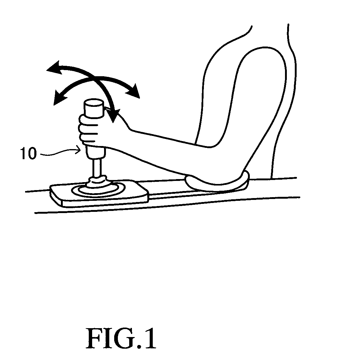
[0029]An embodiment of a vehicle operating apparatus according to the present invention will now be explained while referring to the drawings. This vehicle operating apparatus has the operating lever (joy stick) 10 shown in FIG. 1 as an operating member. The operating lever 10 is provided in the vicinity of the driver's seat in a console box of a vehicle. As shown by the arrows in FIG. 1, it is tilted by the driver backwards and forwards and to the left and right.

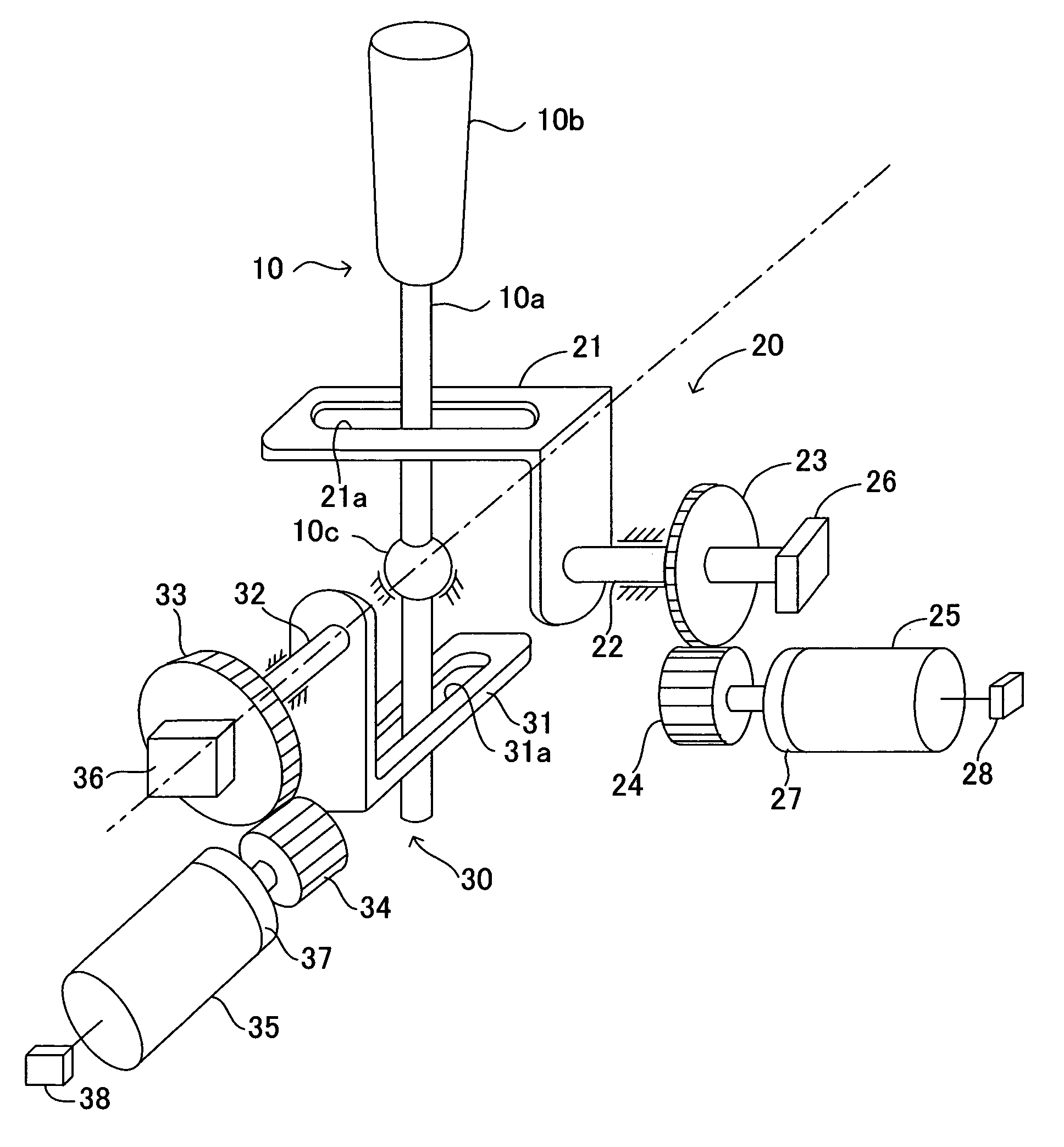
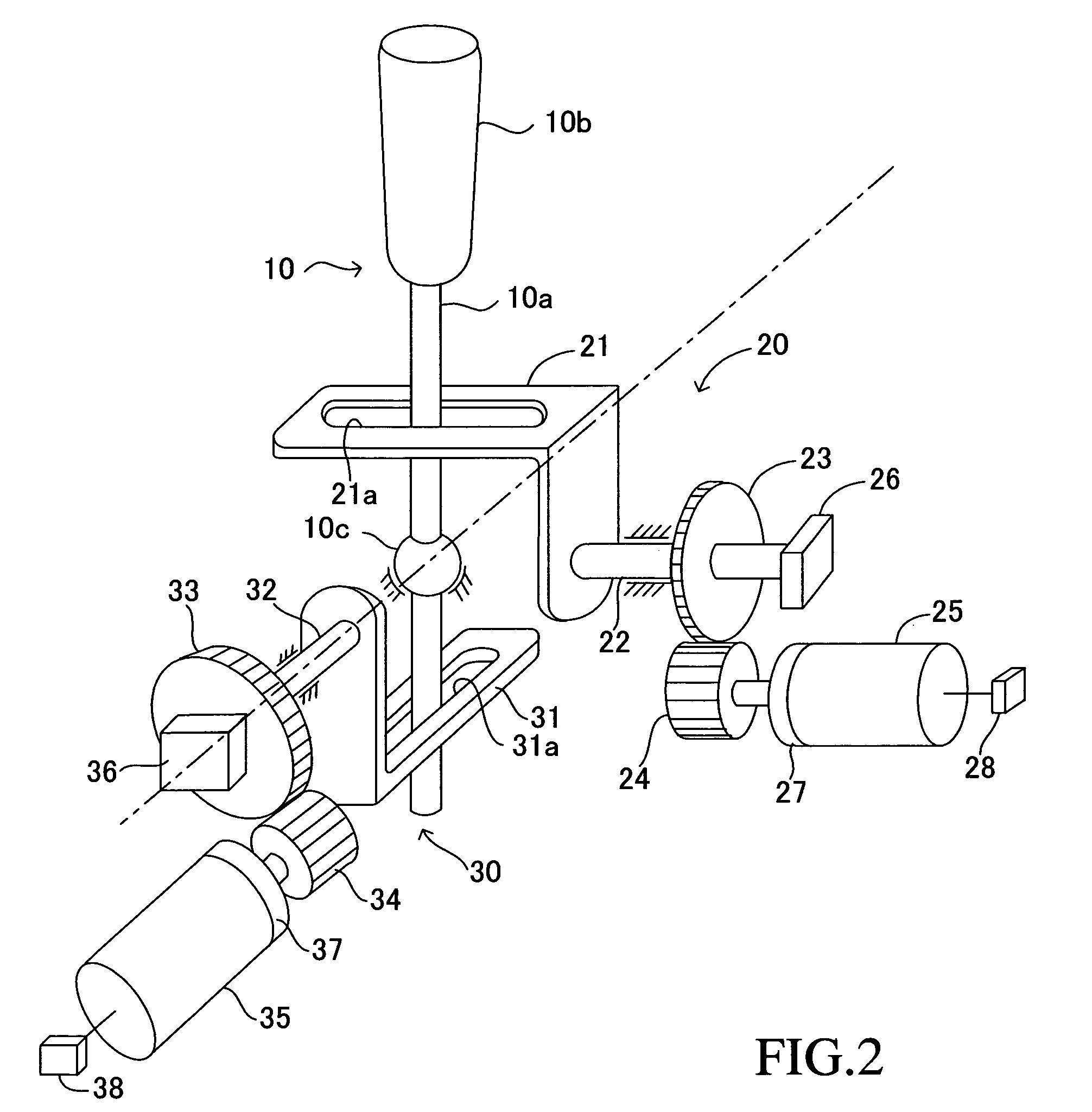
[0030]FIG. 2 is a schematic perspective view of an operating lever apparatus including the operating lever 10. The operating lever 10 includes a cylindrical rod-shaped rod 10a and a cylindrical grip 10b which is secured to the outer periphery of the upper end of the rod 10a. The rod 10a has a spherical portion 10c at approximately its center. The rod 10a is supported via the spherical portion 10c so as to be able to rotate to the left and right and forwards and backwards with respect to the vehicle body.

[0031]The operating ...


PUM


Abstract

A vehicle operating apparatus which accelerates, decelerates and steers a vehicle in accordance with the operation of the operating lever is provided with a reaction force generating means which generates a reaction force opposing the operating lever, a current sensor which senses failure of the reaction force, and an electric control apparatus which decreases the responsiveness of driving control to the operating lever when a failure is sensed. A steering control apparatus provides driving control equal to that of the state prior to the sensing of a failure when the operating speed of the operating lever at the time of the failure exceeds a prescribed value. Additionally, at the time of detection of a failure, an electric control apparatus reduces vehicle speed by an engine control apparatus.

Description

TECHNICAL FIELD[0001]This invention relates to a vehicle operating apparatus which generates a reaction force opposing an operating member operated by a driver in accordance with the amount of displacement of the operating member and performs driving control of a vehicle.BACKGROUND ART[0002]From in the past, as disclosed, for example, in Japanese Patent Application Laid-Open (kokai) No. Hei 11-192960, there have been vehicles in which a joy stick is used as an operating member, and steering, braking, and acceleration of the vehicle is carried out by tilting the joy stick to the left and right and forward and backward with respect to the vehicle. In such vehicles, a reaction force generating mechanism is provided which generates a reaction force opposing the joy stick in accordance with the amount of operation of the joy stick, and as a result of the reaction force generated by the reaction force generating mechanism, stable driving operation of the vehicle is carried out by a driver...

Claims


Application Information

Patent Timeline
Patent Type & Authority Patents(United States)
IPC IPC(8): B62D1/12B62D5/00B60K26/02B62D5/04B62D6/00B62D101/00B62D113/00B62D119/00B62D121/00F02D11/02F02D11/10G05G5/03G05G9/047
CPCB62D1/12B62D5/006B62D5/0484F02D11/02F02D11/10G05G5/03B62D6/008B60K26/02G05G2009/04766F02D11/107B60T8/00B62D1/14B62D6/00
Inventor YANAKA, AKIHIROIKEDA, KOICHI
Owner TOYOTA JIDOSHA KK
Learn More