Gas sensor

a technology of gas sensor and sensor element, which is applied in the direction of instruments, structural/machine measurement, material analysis, etc., can solve the problems of decreasing the time required for the measured gas to reach the sensor element, so as to increase the responsiveness of the gas concentration detection process, prevent the reduction of the sensitivity of the detection of the sensor element, and increase the power consumption

Active Publication Date: 2016-01-14
NGK INSULATORS LTD
View PDF0 Cites 26 Cited by
  • Summary
  • Abstract
  • Description
  • Claims
  • Application Information

AI Technical Summary

Benefits of technology

[0006]For such a gas sensor, a demand for rapidly detecting a change in the gas concentration in measured gas, that is, a demand for increasing the responsiveness of a gas concentration detection process has arisen. In addition, a demand for preventing the sensor element from being cooled by the gas flow of the measured gas or deposition of water has arisen in order to prevent a decrease in the sensitivity of detection of the sensor element or an increase in power consumption of a heater that keeps the sensor element warm. If, for example, a flow channel of the measured gas inside the protection cover is simplified in order to increase the responsiveness of a gas concentration detection process, the flow rate of the measured gas around the sensor element increases and, thus, the sensor element is easily cooled. In contrast, if the flow channel inside the protection cover is complicated in order to prevent the sensor element from being cooled, the time required for the measured gas to reach the sensor element increases and, thus, the responsiveness of a gas concentration detection process decreases. Thus, there is a need for a gas sensor that provides both quick responsiveness and excellent heat retaining properties.

Problems solved by technology

In contrast, if the flow channel inside the protection cover is complicated in order to prevent the sensor element from being cooled, the time required for the measured gas to reach the sensor element increases and, thus, the responsiveness of a gas concentration detection process decreases.

Method used


Image

  • Gas sensor
  • Gas sensor
  • Gas sensor

Examples


experimental example 1

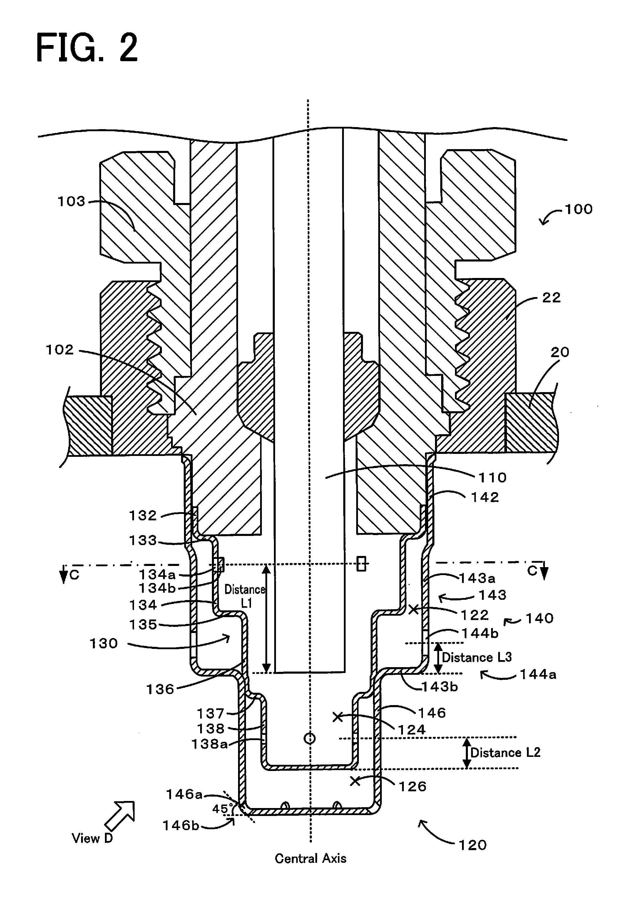
[0089]The gas sensor 100 illustrated in FIGS. 2 to 12 serves as Experimental Example 1. More specifically, the inner protection cover 130 is 0.3 mm in thickness and is 17.7 mm in length in the axial direction. The large-diameter portion 132 is 1.8 mm in length in the axial direction. The first body portion 134 is 5.4 mm in length in the axial direction. The second body portion 136 is 5.6 mm in length in the axial direction. The tip end portion 138 is 4.9 mm in length in the axial direction. The external diameter of the large-diameter portion 132 is 14.1 mm. The external diameter of the first body portion 134 is 11.8 mm. The external diameter of the second body portion 136 is 8.2 mm. The external diameter of the tip end portion 138 is 5.9 mm. The first-inner-hole count Nin of the first inner gas holes 134a is 3. The first-inner-hole average area Ain is 0.200 mm2. The distance L1 is 6 mm. The first-inner-hole non-existence maximum angle θinmax is 115°. The formed angle θ1 is 38°. The ...

experimental examples 2 to 12

[0090]Experimental Examples 2 to 11 are configured by changing the values of the first-outer-hole count Nout, the first-inner-hole count Nin, the inner / outer hole count ratio Nr, the first-outer-hole average area Aout, the first-inner-hole average area Ain, the inner / outer hole-area ratio Ar, the horizontal hole non-existence maximum angle θhmax, the vertical hole non-existence maximum angle θvmax, the first-outer-hole non-existence maximum angle θoutmax, the first-inner-hole non-existence maximum angle θinmax, and the distance L1 of the gas sensor of Experimental Example 1 to those indicated by Table 1. More specifically, Experimental Example 2 is configured as follow. That is, the shape of the inner protection cover is changed into the shape of the inner protection cover 230 of the gas censor 200 illustrated in FIGS. 13 and 14. The first-inner-hole count Nin=6. The inner / outer hole count ratio Nr=0.5. The first-inner-hole non-existence maximum angle θinmax=55°. The other values ar...

experimental examples 12 to 13

[0097]The following gas sensor is configured as Experimental Example 12. That is, all the 12 first outer gas holes are horizontal holes. The other values are the same as those of Experimental Example 2. In addition, the following gas sensor is configured as Experimental Example 13. That is, all the 12 first outer gas holes are the vertical holes. The other values are the same as those of Experimental Example 2. FIGS. 20 and 21 are cross-sectional views illustrating the arrangement of the first inner gas holes and the first outer gas holes of Experimental Examples 12 and 13, respectively. Table 2 shows the first-outer-hole count Nout, the number of horizontal holes, and the number of vertical holes of Experimental Examples 2, 12, and 13. Note that in Experimental Examples 12 and 13, the first inner gas holes are formed at equal intervals, and the first outer gas holes are formed at equal intervals.

[0098][Evaluation Test 2]

[0099]A test that is the same as the evaluation test 1 was con...


PUM

PropertyMeasurementUnit
areaaaaaaaaaaa
areaaaaaaaaaaa
areaaaaaaaaaaa

Abstract

First inner gas holes 134a and first outer gas holes 144a of a gas sensor are formed so that the following conditions are satisfied: a first-inner-hole count Nin≧3, 0<an inner/outer hole count ratio Nr≦0.5, and 0<an inner/outer hole-area ratio Ar≦0.25, where the first-inner-hole count Nin represents the number of first inner gas holes 134a, a first-inner-hole average area Ain [mm2] represents (the total opening area of the first inner gas holes 134a)/(the first-inner-hole count Nin), a first-outer-hole count Nout represents the number of the first outer gas holes 144a, a first-outer-hole average area Aout represents (the total opening area of the first outer gas holes 144a)/(the first-outer-hole count Nout), the inner/outer hole count ratio Nr represents the first-inner-hole count Nin/the first-outer-hole count Nout, and the inner/outer hole-area ratio Ar represents the first-inner-hole average area Ain/the first-outer-hole average area Aout.

Description

BACKGROUND OF THE INVENTION[0001]1. Field of the Invention[0002]The present invention relates to a gas sensor.[0003]2. Description of the Related Art[0004]A gas sensor that detects the concentration of predetermined gas, such as NOx or oxygen, in gas to be measured (e.g., exhaust gas of a motor vehicle) has been known. Such a gas sensor may be cracked since, for example, water generated when an engine starts is deposited onto a sensor element and, thus, the temperature of the sensor element drops. To prevent such an issue, a technique to attach a protection cover to cover the sensor element is proposed. For example, PTL 1 describes a gas sensor having a double structure protection cover provided on the outer periphery of the tip end portion of the sensor element and having a vent hole for leading exhaust gas to the inside.CITATION LISTPatent Literature[0005]PTL 1: JP 2011-112557 ASUMMARY OF INVENTION[0006]For such a gas sensor, a demand for rapidly detecting a change in the gas conc...

Claims


Application Information

Patent Timeline
Patent Type & Authority Applications(United States)
IPC IPC(8): G01M15/10G01N33/00
CPCG01N33/0036G01M15/104G01M15/102G01N33/0037G01N27/4077Y02A50/20
Inventor SEKIYA, TAKAYUKIMURAKAMI, MIKASOKAWA, SHINGOOKABE, YOSUKE
Owner NGK INSULATORS LTD
Why Eureka
Try Eureka