Position control apparatus

a technology of position control and control apparatus, which is applied in the direction of program control, electric controllers, instruments, etc., can solve the problems of loss of the effect of suppressing load change disturbance or reducing position error in transient response, and reducing rigidity of working parts of feed-axis, etc., to suppress low-frequency vibration, reduce rigidity, and suppress low-frequency vibration

Active Publication Date: 2012-08-02
OKUMA CORP
View PDF8 Cites 24 Cited by
  • Summary
  • Abstract
  • Description
  • Claims
  • Application Information

AI Technical Summary

Benefits of technology

[0047]To solve the above-described problem, an aspect of the present invention provides a driven member position control apparatus that includes a motor position detector and a driven member position detector capable of detecting a driven member driven by a motor and is configured to perform full-closed control for controlling the position of the driven member. The position control apparatus includes a subtracter configured to calculate a deflection that represents a difference between a position detection value obtained by the motor position detector and a position detection value obtained by the driven member position detector; an adder configured to calculate a position feedback value by adding an output of a first-order delay circuit that receives the deflection and the position detection value obtained by the motor position detector; a speed command calculator configured to output a speed command value by proportionally amplifying a deviation between the position feedback value and a position command value input from a host apparatus; a differentiator configured to calculate a speed feedback value by differentiating the position detection value obtained by the motor position detector; a torque command calculator configured to output a torque command value by proportionally and integrally amplifying a deviation between the speed feedback value and the speed command value; a mechanism configured to drive the motor according to the torque command value; and an aging corrector configured to receive the position command value and the position detection value obtained by the driven member position detector and control a time constant of the first-order delay circuit in such a way as to increase the time constant when a vibratory state of the driven member is detected, wherein the position control apparatus suppresses low frequency vibrations occurring when a mechanical resonance frequency decreases due to aging.
[0048]Further, another aspect of the present invention provides a driven member position control apparatus that includes a motor position detector and a driven member position detector capable of detecting a driven member driven by a motor and is configured to perform full-closed control for controlling the position of the driven member. The position control apparatus includes a speed command calculator configured to output a speed command value by proportionally amplifying a deviation between a position feedback value, which is a position detection value obtained by the driven member position detector, and a position command value input from a host apparatus; a differentiator configured to calculate a motor speed detection value by differentiating a position detection value obtained by the motor position detector; a differentiator configured to calculate a driven member speed detection value by differentiating the position detection value obtained by the driven member position detector; an adder configured to calculate a speed feedback value by adding the motor speed detection value and an output of a first-order delay circuit that receives a difference between the motor speed detection value and the driven member speed detection value; a torque command calculator configured to output a torque command value by proportionally and integrally amplifying a deviation between the speed feedback value and the speed command value; a mechanism configured to drive the motor according to the torque command value; and an aging corrector configured to receive the position command value and the position detection value obtained by the driven member position detector and control a time constant of the first-order delay circuit in such a way as to increase the time constant when a vibratory state of the driven member is detected, wherein the position control apparatus suppresses low frequency vibrations occurring when a mechanical resonance frequency decreases due to aging.
[0052]When the position control apparatus according to the present invention is employed for a feed-axis driving mechanism in which the magnitude of a torque disturbance (e.g., sliding friction) acting on a driven member is variable, the aging corrector detects a vibratory state occurring due to a reduction in the rigidity of a working part of the feed-axis and increases the time constant Tp of the first-order delay circuit of the position detection value calculation unit, or the time constant Tv of the first-order delay circuit of the speed detection value calculation unit. As a result, the position control apparatus can operate the driven member appropriately while suppressing low-frequency vibrations even when the rigidity of a working part of the feed-axis decreases. Further, the position control apparatus reduces gain setting values of the speed command calculator and the torque command calculator, if necessary. As a result, the position control apparatus can operate the driven member appropriately while suppressing low frequency vibrations even when the rigidity of a working part of the feed-axis decreases, and can minimize the reduction in the responsiveness of the control system.

Problems solved by technology

However, the rigidity of a working part of the feed-axis may decrease due to aging (e.g., frictional wear and looseness) of a component that constitutes a driving mechanism, or due to reduction in tensile strength of a ball screw that is derived from expansion of the ball screw, which may occur when the temperature increases during a continuous operation.
However, if the gain margin is increased excessively, the control system deteriorates in responsiveness.
In some cases, the effect of suppressing the load change disturbance or the effect of reducing the position error in a transient response maybe lost.
As a result, the control system may deteriorate in responsiveness.
Therefore, it is difficult to accurately detect the magnitude of the sliding friction Fd.
More specifically, in a driving mechanism including a driven member subjected to a sliding friction that is variable, it is difficult to detect a reduction in the rigidity of a working part of the feed-axis based on the deflection Ps.
However, the control system greatly deteriorates in command responsiveness, although reducing the gain Kp is effective for stabilizing the control system.
However, the motor position detection value Pm will deteriorate in responsiveness.
Further, it is unable to adjust the time constant of a first-order delay circuit, which is required to calculate a position / speed feedback value, to an appropriate value according to the degree of reduction in the rigidity of a working part of the feed-axis.
As a result, if an excessively large gain margin is secured, the control system may deteriorate in responsiveness.
On the other hand, if the secured gain margin is smaller, low frequency vibrations may occur in a driven member.

Method used


Image

  • Position control apparatus
  • Position control apparatus
  • Position control apparatus

Examples


Embodiment Construction

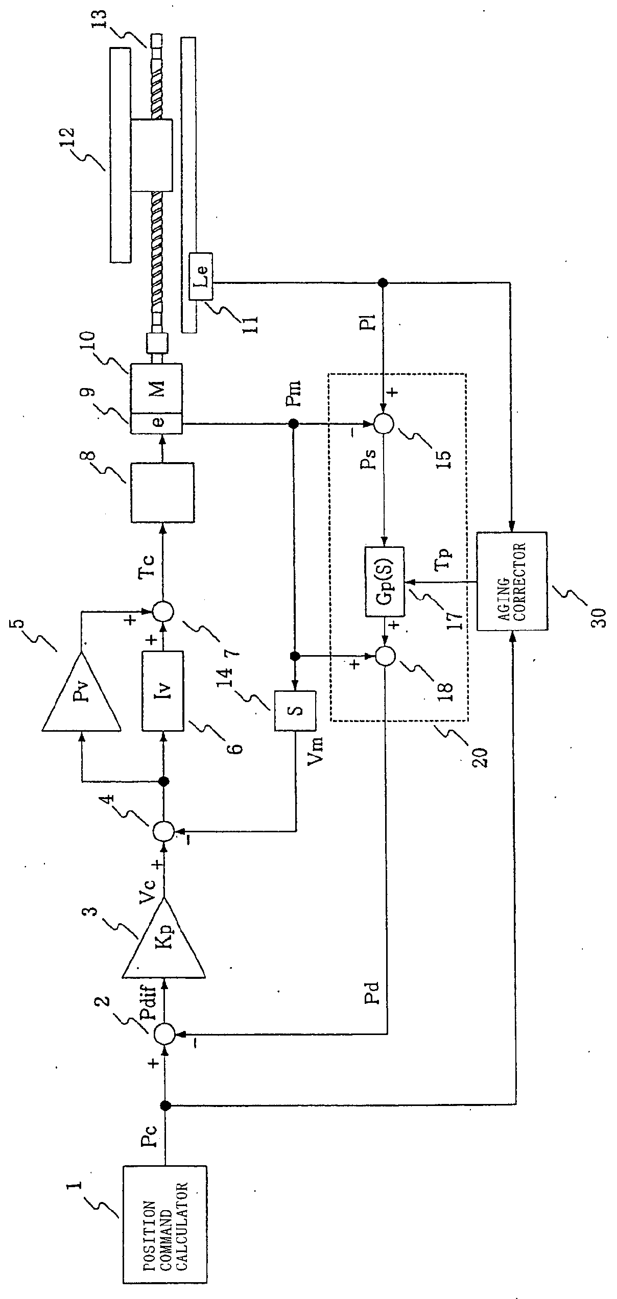
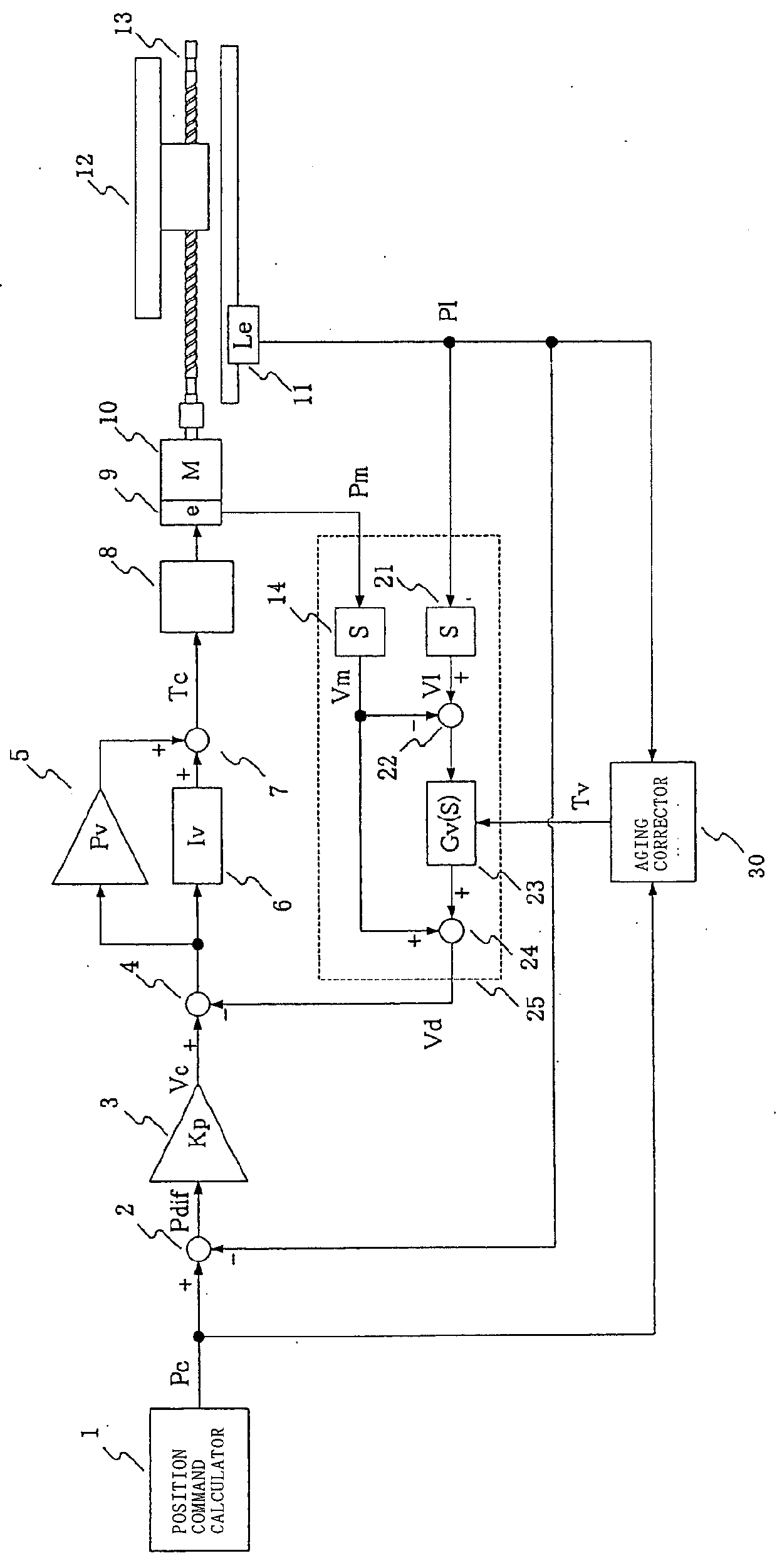
[0069]An embodiment of the present invention is described below. Components similar to those illustrated in FIGS. 4 to 8 are denoted by the same reference numerals and their descriptions are not repeated. Each of FIG. 1 and FIG. 2 illustrates a control block diagram according to the present invention. An aging corrector 30 receives the position command Pc and the driven member position detection value Pl and detects a vibratory state of a driven member when a driving mechanism is not in an acceleration / deceleration state. Further, if a vibratory state of the driven member is detected, the aging corrector 30 changes the time constants Tp and Tv to be used in the first-order delay circuits 17 and 23.

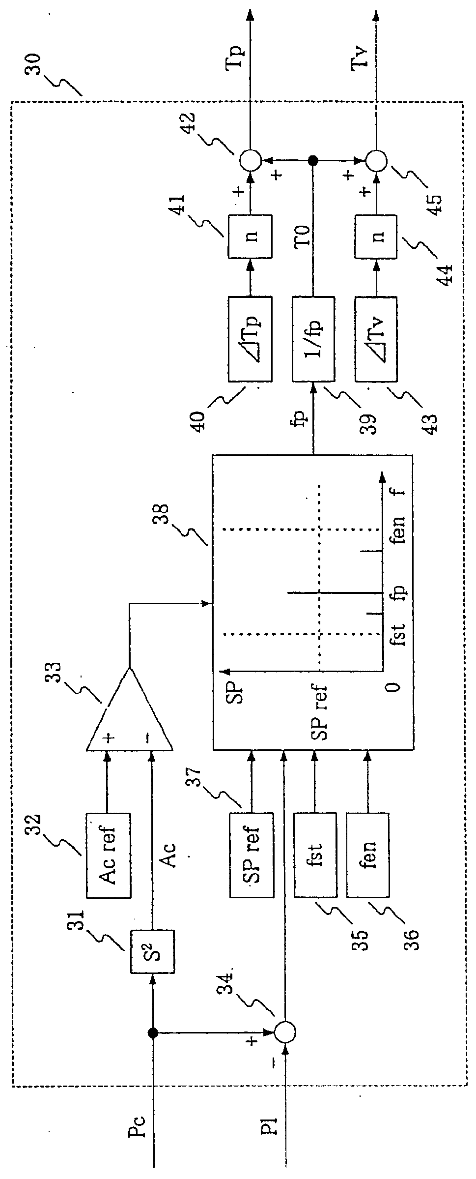
[0070]FIG. 3 illustrates an example of the aging corrector 30 that can change the time constants Tp and Tv. The position command value Pc is input to a second-order differentiator 31. The second-order differentiator 31 calculates an acceleration command Ac by obtaining a two-order derivati...


PUM


Abstract

A position control apparatus calculates a position detection value by adding an output of a first-order delay circuit 17 that receives a difference between a driven member position detection value Pl and a motor position detection value Pm to the motor position detection value Pm, and uses the obtained position detection value as a position feedback value. An aging corrector 30 suppresses low frequency vibrations by controlling a time constant Tp of the first-order delay circuit 17 in such a way as to increase the time constant when a vibratory state of the driven member is detected.

Description

PRIORITY INFORMATION[0001]This application claims priority to Japanese Patent Application Nos. 2011-016321, filed on Jan. 28, 2011, and 2011-283744, filed on Dec. 26, 2011, which are incorporated herein by reference in their entireties.BACKGROUND[0002]1. Technical Field[0003]The present invention relates to a position control apparatus for a feed-axis (i.e., a driven member, such as a table, a saddle, or a spindle head) of a machine tool or the like. More specifically, the present invention relates to an improved position control apparatus capable of realizing full-closed control in controlling the position of a driven member based on a position command value.[0004]2. Related Art[0005]The following conventional techniques are available to reduce a position error in a position control apparatus that includes a linear scale attached to a movable portion of a machine tool to detect the position of a driven member and performs full-closed control based on a comparison between a detected...

Claims


Application Information

Patent Timeline
Patent Type & Authority Applications(United States)
IPC IPC(8): G05B11/32G05B15/02
CPCG05B19/404G05B2219/41128G05B2219/37498
Inventor MIYAJI, MASASHI
Owner OKUMA CORP
Why Eureka
Try Eureka