
Franking device with tamper protection

a technology of tampering protection and printing device, which is applied in the direction of ticket-issuer equipment, printing, instruments, etc., can solve the problems of ingenious printing, data is far more difficult for a tamperer to obtain, or cannot be obtained at all, so as to reduce the risk of such tampering

Inactive Publication Date: 2007-02-20
FRANCOTYP POSTALIA
View PDF6 Cites 1 Cited by
  • Summary
  • Abstract
  • Description
  • Claims
  • Application Information

AI Technical Summary

Benefits of technology

[0009]An object of the present invention is to provide a method and an apparatus of the type initially described wherein the risk of such tampering is reduced in a simple way.
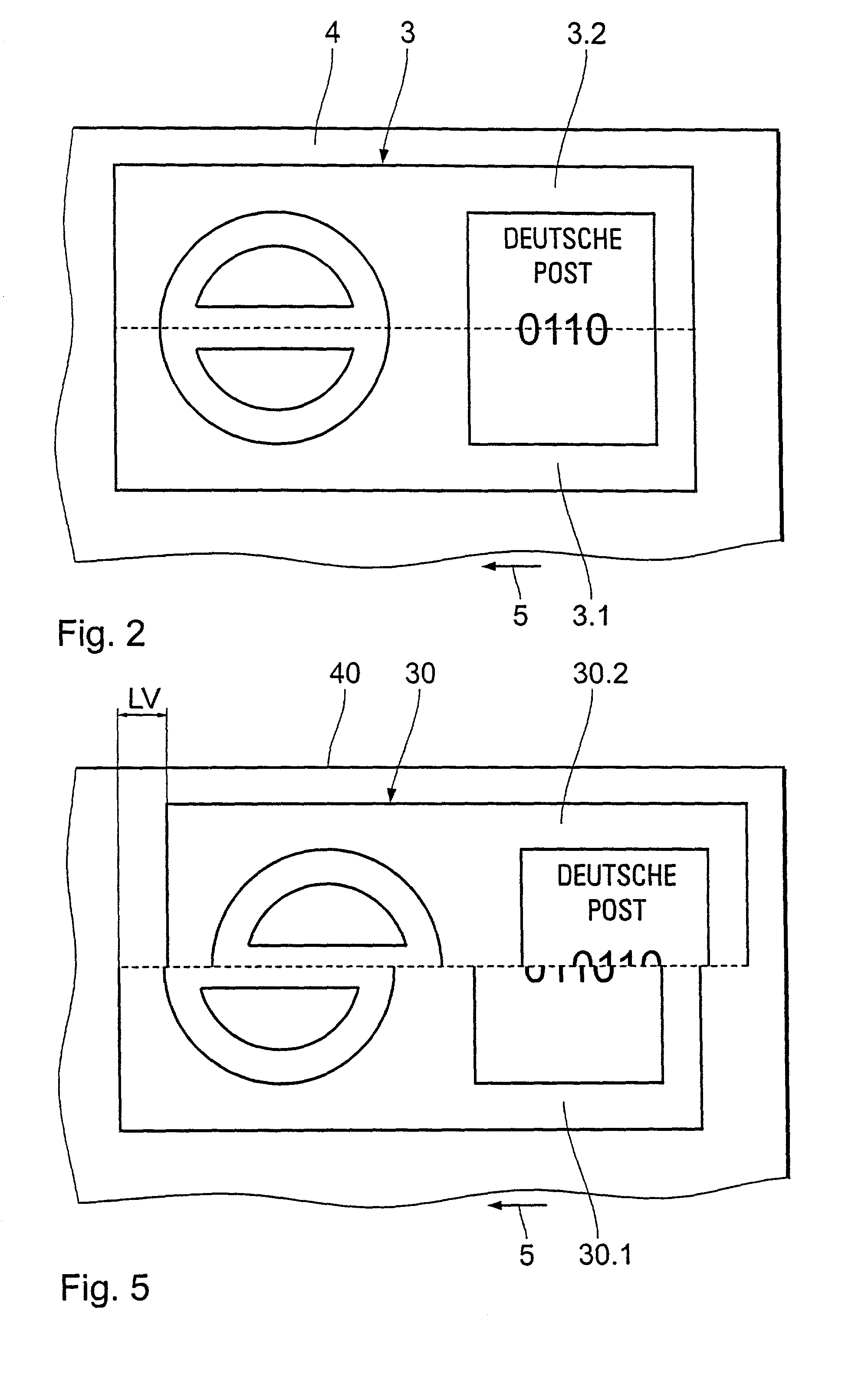
[0014]If a tamperer nonetheless attempts such a parallel attack, the result that will usually be obtained with a printer device connected parallel is a printout wherein the two partial images are offset relative to one another by a relatively large amount along the first direction. This longitudinal offset usually can be relatively simply detected; if it is large enough it can even be recognized with the naked eye, so that a mailing that is provided with such a franking imprint can be simply separated out upon visual inspection, for example in a mail distribution center. Since franking imprints also frequently contain an indication of the postage meter machine with which they were generated, mailings with counterfeit franking imprints not only can be prevented from being delivered, but also the postage meter machine that was manipulated in order to produce the counterfeit can be identified.
[0020]By means of the selected variation of the waiting time interval, the longitudinal offset can be selected so large that it can be detected in an arbitrary way. Preferably, however, the size range of the longitudinal offset is selected such that the longitudinal offset can be detected optically, for example with the image recognition devices as are usually utilized in mail distribution centers. Preferably, the size range of the longitudinal offset is selected such that the longitudinal offset can be recognized with the naked eye, so that the probability of discovering an attempted fraud is further enhanced.

Problems solved by technology

In the case of a printer device connected in parallel with other devices in a fraudulent way, the synchronization between the control of the drive generating the relative motion between the print head and the image carrier which occurs in the control of the print elements of the print head is inventively made more difficult by the time between the end of the print event in the first step and the beginning of the print even in third step being varied according to the predetermined function.
Such data are far more difficult for a tamperer to obtain, or cannot be obtained at all, since the drive controller and the motor are inaccessibly accommodated in the secure housing part of the postage meter machine.

Method used


Image

  • Franking device with tamper protection
  • Franking device with tamper protection
  • Franking device with tamper protection

Examples


Embodiment Construction

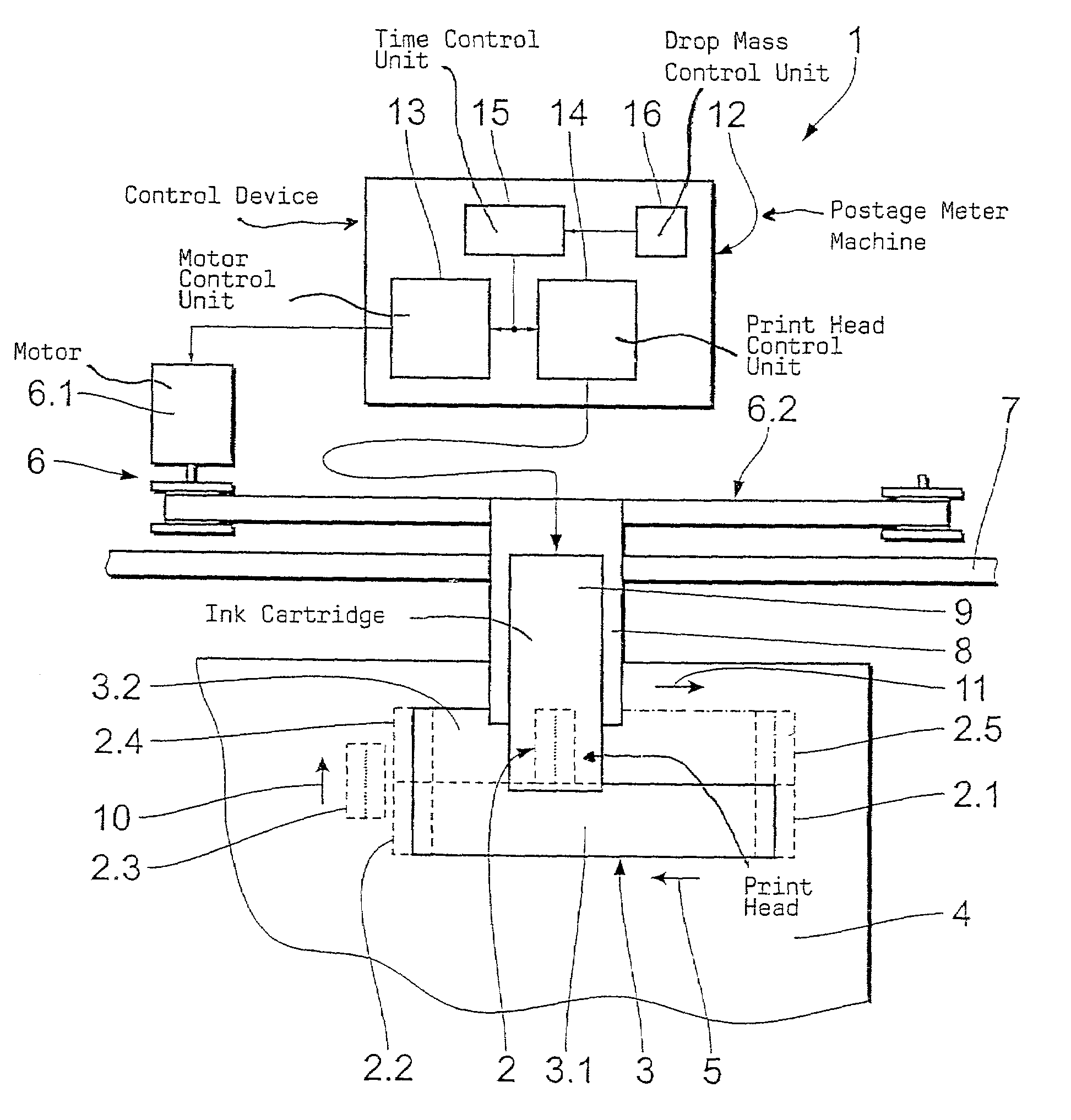
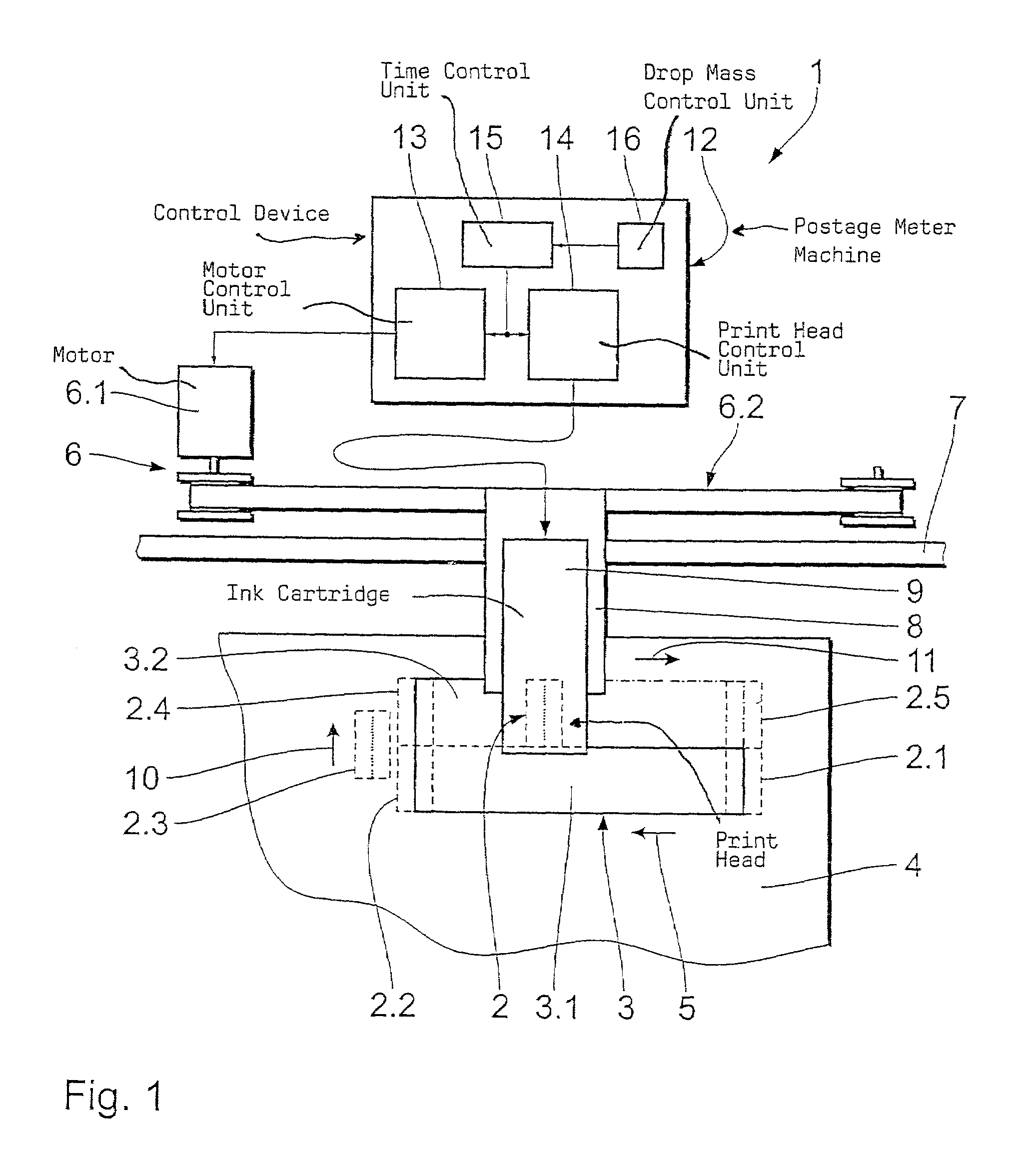
[0033]FIG. 1 is a schematic illustration of a portion of an inventive apparatus in the form of a postage meter machine 1 having a print head 2 for generating a print image in the form of a franking imprint 3 on a letter for representing an image carrier. The franking imprint 3 is composed of two partial images 3.1 and 3.2 offset transversely relative to a first direction 5, that supplement one another to form the franking imprint 3.

[0034]For generating the two partial images 3.1 and 3.2, a first drive unit 6 having a motor 6.1 and a belt 6.2 driven by the motor 6.1 are provided, the belt 6.2 being in turn connected to a mount 8 conducted through a longitudinal guide 7 along the first direction 5. A cartridge 9 with the print head 2 is seated in the mount 8 so as to be displaceable transversely to the first direction 5. The cartridge 9 and thus the print head 2 can thereby be offset transversely to the first direction 5 with a second drive unit (not shown).

[0035]The cartridge 9 in th...


PUM


Abstract

In a method and apparatus for generating a print image, particularly a franking imprint, on a first image carrier composed of at least one first partial image and a second partial image offset thereto transversely relative to a first direction, whereby a relative motion between a print head and an image carrier is generated along a first direction in a first step for generating the first partial image. A transverse offset between the print head and the image carrier is generated in a second direction proceeding transversely to the first direction in a second step. A relative motion between the print head and the image carrier is generated along the first direction in a third step for generating the second partial image. The waiting time interval between the end of the printing event of the first step and the beginning of the printing event of the third step has a length that is varied according to a prescribed function to prevent tampering.

Description

BACKGROUND OF THE INVENTION[0001]1. Field of the Invention[0002]The present invention is directed to a method and apparatus for generating a print image, particularly a franking imprint, on an image carrier, of the type wherein the print image is composed of at least one first partial image and a second partial image that are transversely offset relative to a direction, wherein a relative motion between a print head and the image carrier is generated along a first direction in a first step for generating the first partial image, a transverse offset between the print head and the image carrier is generated in a second direction proceeding transverse to the first direction in a second step, and a relative motion between the print head and the image carrier is generated along the first direction in a third step for generating the second partial image.[0003]2. Description of the Prior Art[0004]A method and apparatus of the above type are disclosed, for example, in European Application 0...

Claims


Application Information

Patent Timeline
Patent Type & Authority Patents(United States)
IPC IPC(8): B41J29/38G06F17/00G07B17/00
CPCG07B17/00508G07B2017/00532G07B2017/00919G07B2017/00637G07B2017/00564
Inventor LODGE, GRAHAM RODERICK
Owner FRANCOTYP POSTALIA
Learn More