
Planar light-emitting device

a light-emitting device and planar technology, applied in non-linear optics, lighting and heating apparatus, instruments, etc., can solve problems such as color shift phenomenon and backlight module brightness instability, and achieve uniform lighting performance

Active Publication Date: 2007-02-20
EPISTAR CORP
View PDF7 Cites 38 Cited by
  • Summary
  • Abstract
  • Description
  • Claims
  • Application Information

AI Technical Summary

Benefits of technology

The solution provides stable and uniform lighting performance even with variations in light sources, enhancing the reliability of planar displays by mixing and directing light effectively, and incorporating a light detector to maintain desired light quality and quantity.

Problems solved by technology

Whenever any variation of the light sources happens, such as blinking, failure, fading etc., the backlight module becomes unstable in brightness, and color shift phenomenon may occur.

Method used


Image

  • Planar light-emitting device
  • Planar light-emitting device
  • Planar light-emitting device

Examples


Embodiment Construction

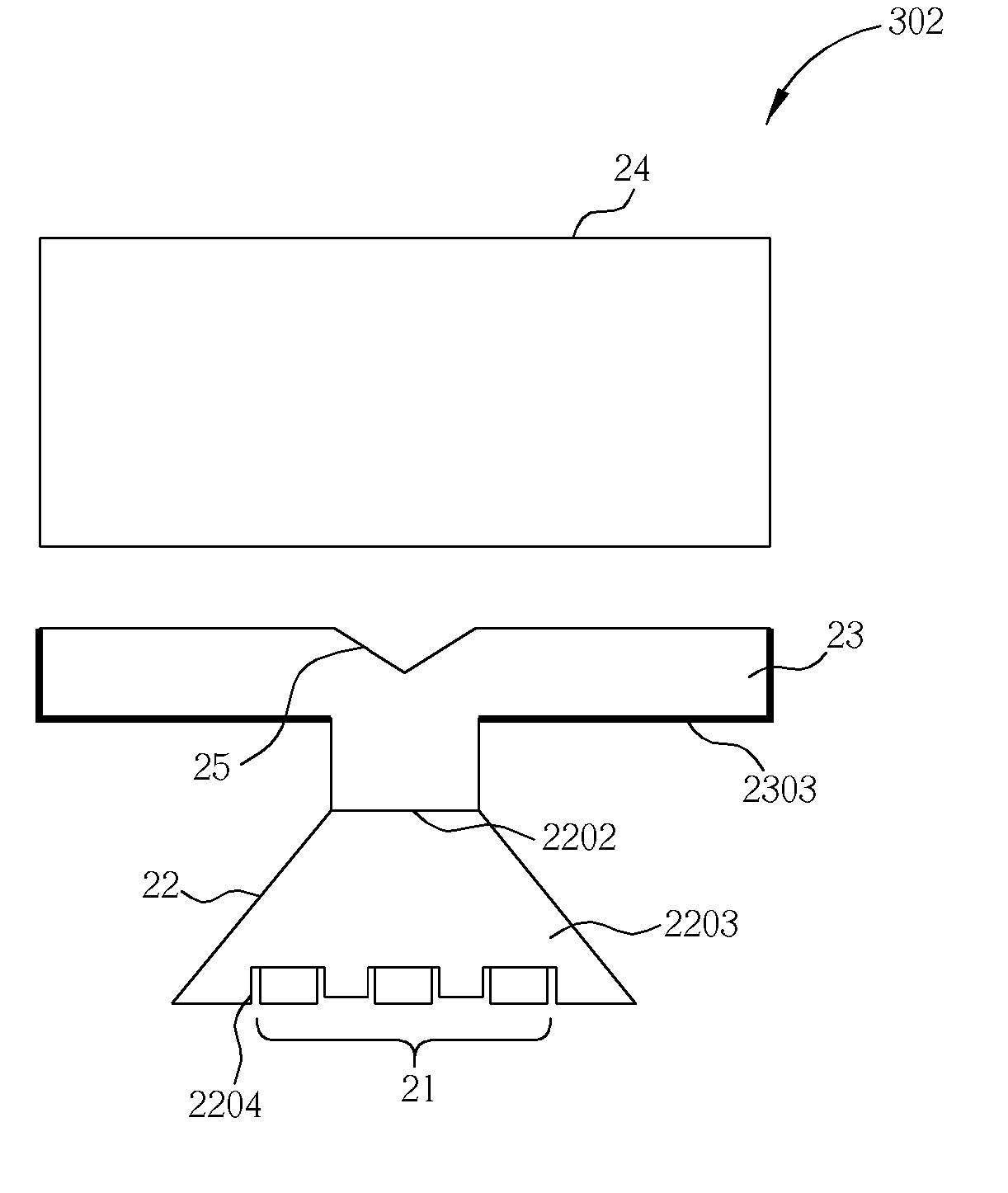
[0017]Please refer to FIG. 3 and FIG. 4. FIG. 3 is a drawing illustrating a planar light-emitting device 301 according to one embodiment of the present invention, and FIG. 4 is a drawing illustrating a planar light-emitting device 302 according to another embodiment of the present invention. The planar light-emitting device 301 comprises light sources 21 and a light gathering module 22 capable of gathering the light generated by the light sources 21. The light emitted by the light sources 21 becomes mixed through the light gathering module 22. A linear light generator 23 receives the mixed light from the light gathering module 22, and a light distributing unit 25 of the linear light generator 23 is capable of transferring most of the mixed light into linear light (not shown). A planar light generator 24 is capable of receiving the linear light from the linear light generator 23 and distributing the linear light into planar light (not shown) which can be used for a planar display or ...


PUM

PropertyMeasurementUnit
areaaaaaaaaaaa
reflecting areaaaaaaaaaaa
scattering areaaaaaaaaaaa

Abstract

A planar light-emitting device includes a light source for generating light, a light gathering module for gathering the light generated by the light source and generating mixed light, a linear light generator comprising a light distributing unit for receiving the mixed light and distributing the mixed light to generate linear light, and a planar light generator for receiving the linear light and generating a planar light.

Description

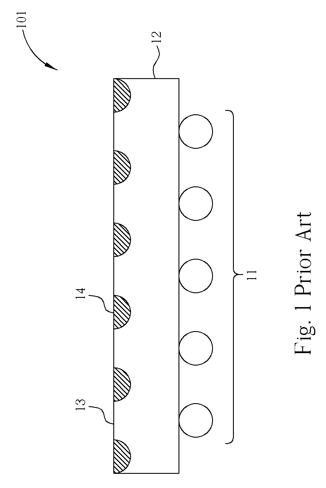
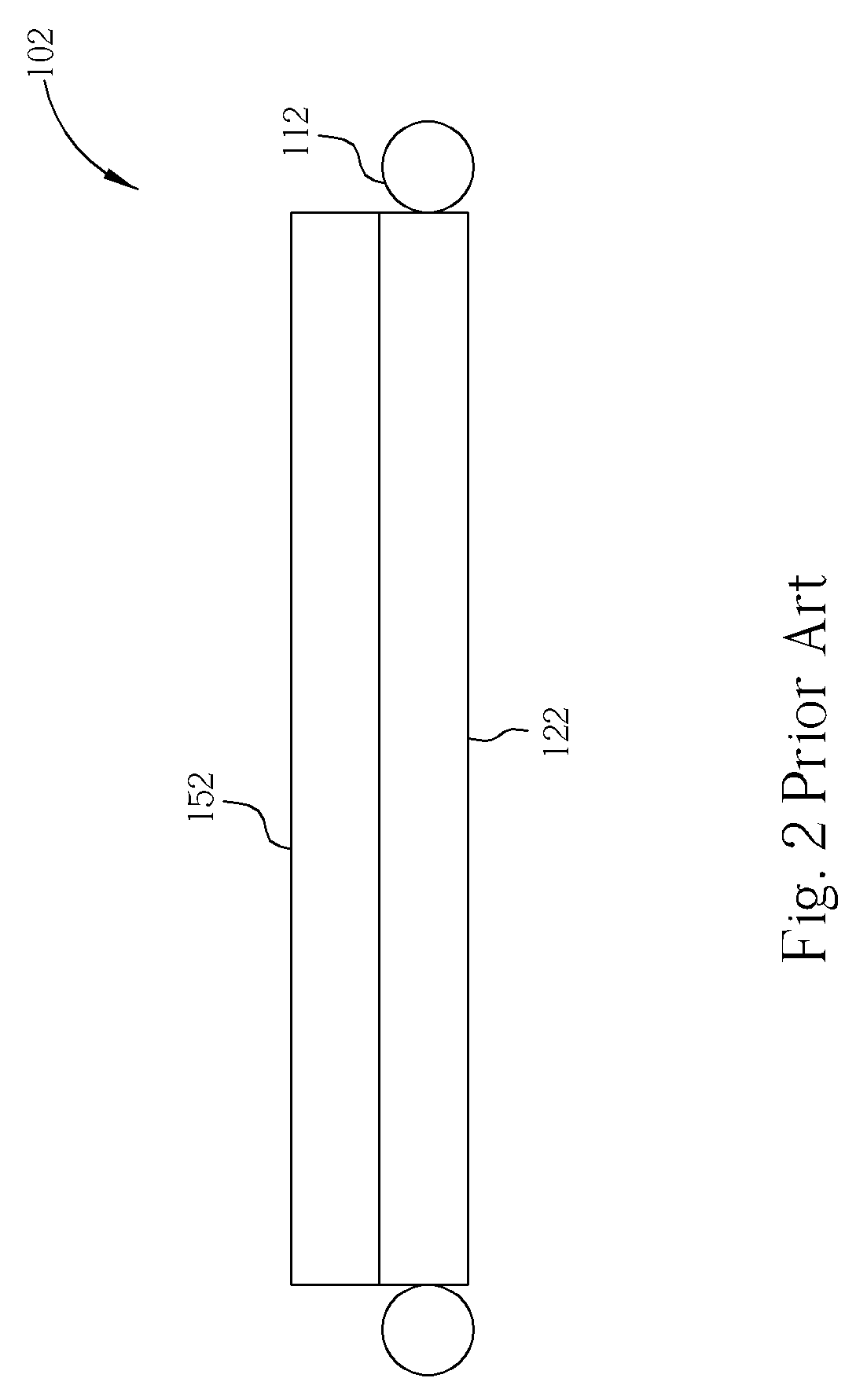
BACKGROUND OF INVENTION[0001]1. Field of the Invention[0002]The present invention relates to a planar light-emitting device, and more particularly, to a planar light-emitting device for gathering and mixing light to generate planar light.[0003]2. Description of the Prior Art[0004]A planar display such as a liquid crystal display (LCD) is a passive display, i.e., it requires a device functioned as a light source, to provide a planar or linear light, and this device is usually called a backlight module. There are usually two types of backlight modules, one is the direct type backlight, and the other is the edge light type backlight.[0005]FIG. 1 illustrates a conventional direct type backlight module 101. The direct type backlight module 101 includes a set of light sources 11, a liquid crystal display panel (not shown), which being placed above the direct type backlight module 101, and an optical conditioning component 12, such as a diffuser and / or a prism sheet etc. The light sources ...

Claims


Application Information

Patent Timeline
Patent Type & Authority Patents(United States)
IPC IPC(8): F21V9/00G02B6/00F21S2/00F21V7/22F21V8/00F21Y101/02G02F1/13357G09F13/14H01P5/00
CPCG02B6/0028G02B6/0018G02F2001/133607G02B6/0068G02F1/133607
Inventor CHEN, YI-MINGCHEN, JUN-CHUNGYIN, CHOU-CHIHHSU, CHIA-LIANGTSAI, CHIA-FENHSIEH, MIN-HSUN
Owner EPISTAR CORP
Learn More