Voltage regulated light string

a technology of voltage regulation and light strings, applied in the direction of lighting and heating apparatus, color-music instruments, applications, etc., can solve the problems of less efficient power consumption of light strings and almost flicker-free string operation, and achieve the effect of low manufacturing cost, simple and economical construction, and reduced overall cost of manufacturing the final produ

Inactive Publication Date: 2007-02-20
JLJ
View PDF46 Cites 27 Cited by
  • Summary
  • Abstract
  • Description
  • Claims
  • Application Information

AI Technical Summary

Benefits of technology

[0007]The silicon semiconductor shunt of the present invention is designed so that it is always conducting, regardless of whether its associated lamp is “on” or “off”. The shunt operates in either of two low impedance states, or in other words, two conducting levels. By operating the silicon semiconductor shunt between two low impedance conducting levels, better voltage regulation is obtained. Effectively, neither of the two low impedance states rises above several hundred ohms. The operation of the shunt in this invention occurs in the steep part of the electrical current-voltage (IV) curve beyond the “knee” where the slope rises sharply. Although the light string operates somewhat less efficiently in terms of power consumption when operating in this manner, the increased voltage regulation obtained as a consequence of this operation results in an almost flicker-free operation of the string as lights turn on and off. Visually, the effect is highly appealing.
[0009]It is therefore a principal object of the present invention to provide a simple and inexpensive silicon type semiconductor voltage regulator filament shunt, or bypass, for each of a plurality of series connected flasher light bulbs, the filament shunt having a predetermined conductive voltage drop which is only slightly greater than the voltage rating of said bulbs when operating, and the shunt becoming more conductive whenever the peak voltage applied across the shunt exceeds its predetermined voltage drop conductive value. Thus, a continued and uninterrupted flow of current is provided through each of the remaining lamps in the string, together with little apparent change in illumination from the lamps.
[0011]It is another object of the present invention to provide a new series-connected random twinkle light string which has the desirable features of the lamps flashing on and off at various points in time and yet is of very simple and economical construction and is relatively inexpensive to manufacture in mass quantities, thereby keeping the overall cost of manufacturing the final product at a minimum.
[0012]It is still another object of the present invention to provide a series-connected light bulb string in which the light emitted from each flashing incandescent light bulb will optionally appear, disappear, and reappear independently and continuously along the entire string, thereby creating a most striking, novel and unusual twinkling effect.

Problems solved by technology

Although the light string operates somewhat less efficiently in terms of power consumption when operating in this manner, the increased voltage regulation obtained as a consequence of this operation results in an almost flicker-free operation of the string as lights turn on and off.

Method used


Image

  • Voltage regulated light string
  • Voltage regulated light string
  • Voltage regulated light string

Examples


Embodiment Construction

[0019]The present invention now will be described more fully with reference to the accompanying drawings, in which several presently preferred embodiments of the invention are shown. This invention may, however, be embodied in various forms and should not be construed as limited to the embodiments set forth herein. Rather, these embodiments are provided so that this disclosure will be thorough and complete, and will fully convey the scope of the invention to those skilled in the art.

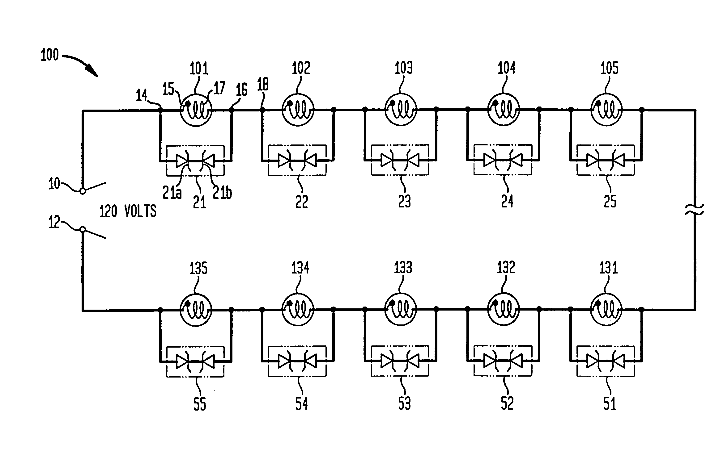
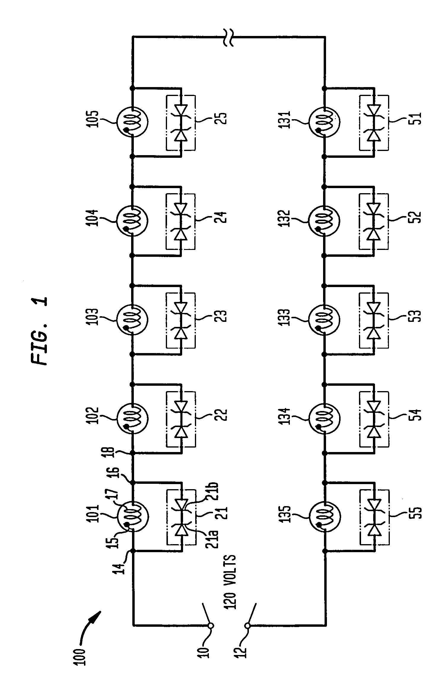
[0020]FIG. 1 shows a schematic diagram of a series connected light string 100 in accordance with the present invention. Input terminals 10 and 12 are adapted to be connected to a suitable electrical source, such as 120–125 volts of alternating current normally found in a typical household or business. Connected to the input terminal 10 is a first terminal 14 of a first electrical flasher light bulb 101. The electrical flasher light bulb 101 may suitably include a bimetallic strip 15 which conducts curren...


PUM


Abstract

A string set of series-connected incandescent flasher type lamps in which substantially all of the lamp filaments in the set are individually provided with a voltage regulated shunt circuit, which includes a voltage responsive silicon semiconductor device, which operates in one of two conducting states, neither of which is greater than about 200 ohms. When the flasher lamp is in the “on” or illuminated state, the silicon semiconductor voltage regulating shunt device is in a low impedance state. When the flasher is in the “off” state, the impedance of the silicon semiconductor device is in a lower impedance state equal to or slightly greater than the parallel equivalent impedance of silicon semiconductor device in parallel with the normal operating impedance of the flasher lamp.

Description

[0001]This is a continuation-in-part of application Ser. No. 10 / 364,526, filed Feb. 12, 2003, now U.S. Pat. No. 6,765,313, which is a continuation of application Ser. No. 10 / 061,223, filed Feb. 4, 2002, now U.S. Pat. 6,580,182, which is a continuation of application Ser. No. 09 / 526,519, filed Mar. 16, 2000, now abandoned, which is a division of application Ser. No. 08 / 896,278, filed Jul. 7, 1997, now abandoned, which is a continuation of application Ser. No. 08 / 653,979, filed May 28, 1996, now abandoned, which is a continuation-in-part of application Ser. No. 08 / 560,472, filed Nov. 17, 1995, now abandoned, which is a continuation-in-part of application Ser. No. 08 / 494,725, filed Jun. 26, 1995, now abandoned.[0002]This application is a continuation of application Ser. No. 10 / 141,156, filed May 8, 2002, now U.S. Pat. No. 6,597,125, which claims the benefit of U.S. Provisional Application Ser. No. 60 / 291,754, filed May 17, 2001, which is incorporated by reference herein in its entirety...

Claims


Application Information

Patent Timeline
Patent Type & Authority Patents(United States)
IPC IPC(8): F21S4/00F21W121/04H05B37/03H05B39/10
CPCH05B39/105H05B37/036H05B47/23
Inventor JANNING, JOHN LOUIS
Owner JLJ
Why Eureka
Try Eureka