Electronic pen, mounting part therefor and method of making the pen

a technology of electronic pen and mounting part, applied in the field of electronic pen, can solve the problems of insufficient precision in recording handwritten information, many pens must be rejected in manufacture, and it is difficult to manufacture the above prior-art pens in large volumes, so as to minimize the number of components included, reduce the number of rejects in manufacture, and reduce the difficulty of manufacturing

Inactive Publication Date: 2007-02-20
ANOTO AB
View PDF19 Cites 36 Cited by
  • Summary
  • Abstract
  • Description
  • Claims
  • Application Information

AI Technical Summary

Benefits of technology

[0030]The inventive method of making an electronic pen comprises the step of arranging a guiding element for a writing means and an imaging detector unit in a common mounting part, thereby allowing great accuracy and few rejects in manufacture.
[0031]According to a variant of the method according to the invention, the guiding element is formed as a portion of the mounting part, preferably as a through hole which is formed for a tight fit with the writing means. This is a rational way of forming the guiding element since it minimizes the number of components included.
[0032]In a variant, a light source is arranged in the mounting part. In this way, a light source for improved detection may be mounted in an efficient and accurate way.
[0033]According to a preferred variant of the method according to the invention, the mounting part is arranged in a forward portion of the pen, which allows the arranged components to be safely mounted in the forward portion of the pen.

Problems solved by technology

However, it may be difficult to manufacture the above prior-art pens in large volumes owing to the long tolerance chains that exist between the components included which convert a physical pen stroke on a writing base into a sequence of positions.
If the tolerance of each individual component is not kept at a minimum, which is costly, the relative positioning of the components will thus vary quite significantly between different items of pens.
As a result, many pens must be rejected in manufacture in that some items have insufficient precision in the recording of handwritten information.
The above prior-art pens are besides sensitive to mechanical shocks since there is a risk that the components inside the pen are displaced relative to each other if, for instance, the pen is dropped onto the floor.
Summing up, also this type of pen has long tolerance chains which may have a detrimental effect on the yield in serial production thereof.

Method used


Image

  • Electronic pen, mounting part therefor and method of making the pen
  • Electronic pen, mounting part therefor and method of making the pen
  • Electronic pen, mounting part therefor and method of making the pen

Examples


Embodiment Construction

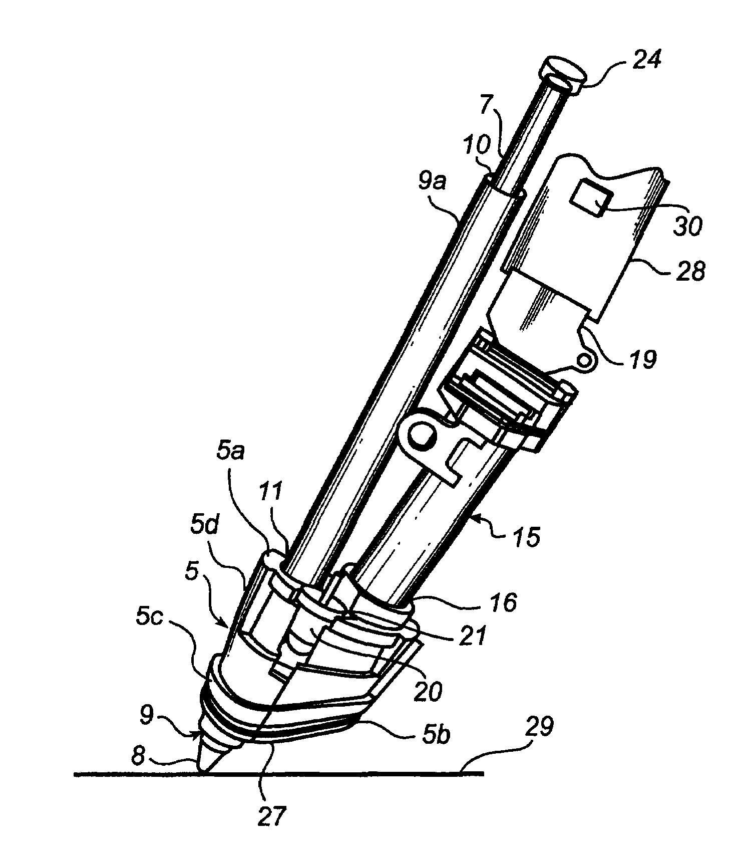
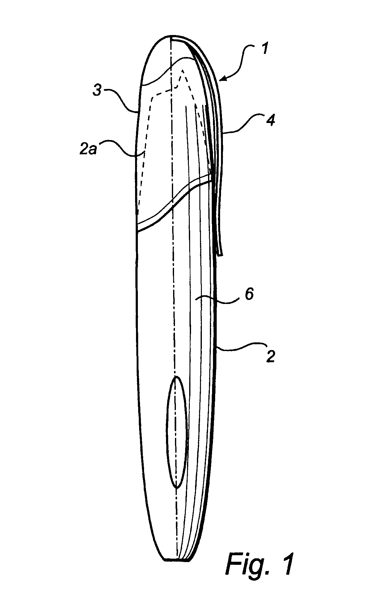
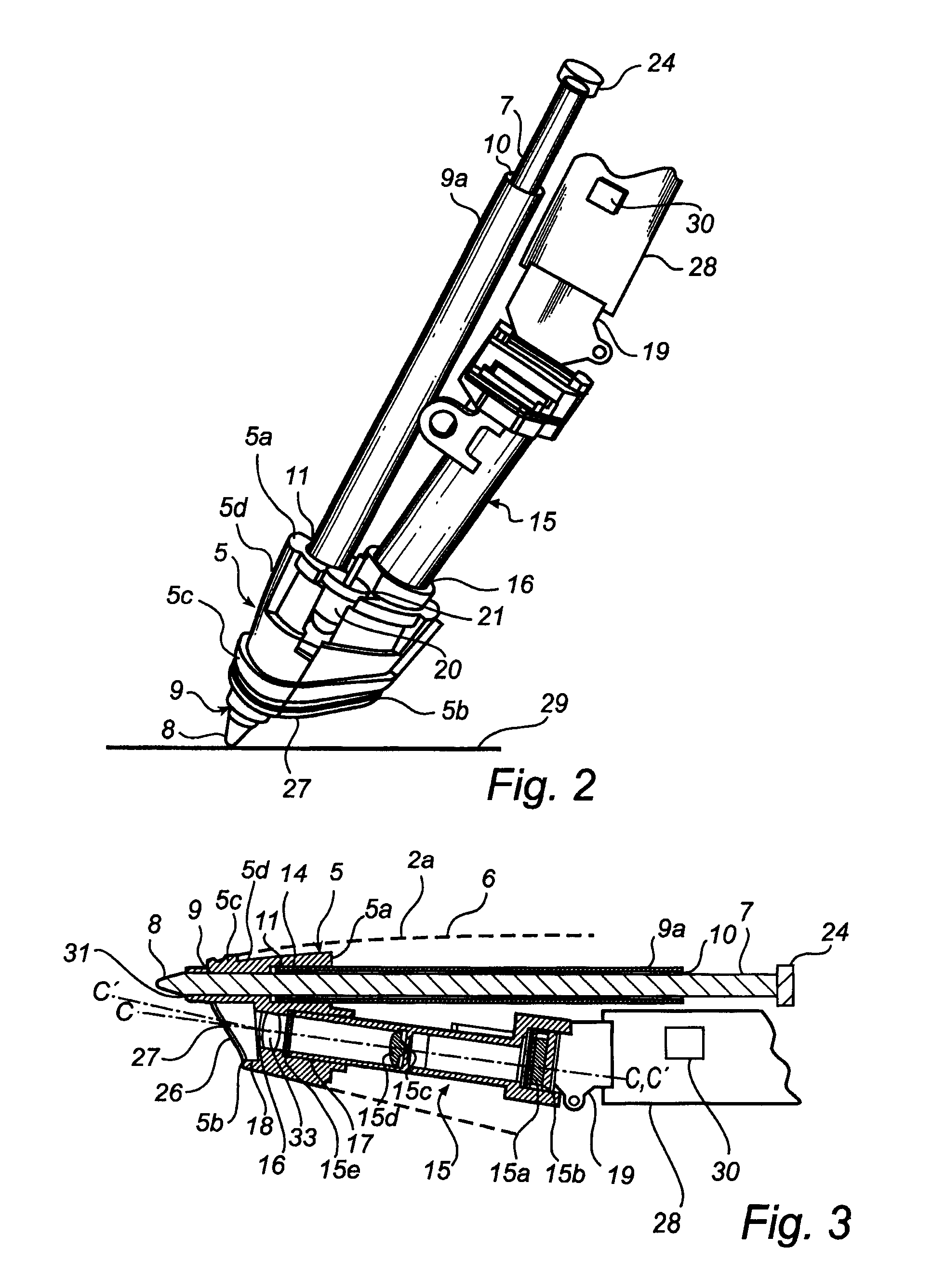
[0042]The electronic pen 1 in FIG. 1 has a body 2 with a forward portion 2a and a cap 3 with a clip 4. In the forward portion 2a of the pen 1, a mounting part 5 is arranged partly inside a casing 6, as illustrated in FIGS. 2 and 3. The mounting part 5 constitutes part of the interior of the pen 1 and has an inner end 5a facing inwards in the casing 6 and an outer end 5b facing out of the casing 6, as shown in FIG. 2. An ink cartridge 7 with a pen point 8 is inserted into a tubular mounting aid 9a and, in the portion adjacent to the pen point 8, inserted into a guiding element in the form of a pen point guide means 9, which in a portion adjacent to the outer end 5b of the mounting part 5 is essentially cylindrical and in a portion adjacent to the inner end 5a of the mounting part 5 widens slightly conically. Between the ink cartridge 7 and the inside of the mounting aid 9a there is a certain play 10. A play (not shown) can correspondingly be found between the ink cartridge 7 and the ...


PUM


Abstract

An electronic pen comprises a writing means (7) which extends into the interior of the pen, a guiding element (9) for the writing means (7), a sensor (15a) for recording images and an image processor (30) for calculating positions of the pen based on said images. The sensor (15a) is part of an imaging detector unit (15). The guiding element (9) and the detector unit (15) are arranged in a common mounting part (5) which is fixedly mounted in the interior of the pen. In such a pen, it is possible to minimize the tolerance chain between the components that convert a pen stroke on a base into a sequence of positions. This enables serial production of the pen with a small number of rejects.

Description

[0001]This application claims priority on provisional Application No. 60 / 301,447 filed on Jun. 29, 2001, the entire contents of which are hereby incorporated by reference.FIELD OF THE INVENTION[0002]The present invention relates to an electronic pen comprising a writing means extending into the interior of the pen, a guiding element for the writing means, a sensor for recording images as well as an image processor for calculating positions of the pen based on said images. The invention also concerns a mounting part for an electronic pen as well as a method of making an electronic pen.BACKGROUND ART[0003]Pens of the type described by way of introduction can be used for, inter alia, electronic recording of handwritten information, as is known from e.g. U.S. Pat. No. 5,652,412, WO 00 / 25293, U.S. Pat. No. 5,294,792, U.S. Pat. No. 5,852,434 and WO 00 / 73983. Here a sensor records, preferably via one or more imaging components, images of an area around or beside the contact point of the wr...

Claims


Application Information

Patent Timeline
Patent Type & Authority Patents(United States)
IPC IPC(8): G09G5/00G06F3/033G06V10/12
CPCG06F3/03542G06K9/24G06F3/03545G06V10/12
Inventor FERMGARD, BJORNSTROMBERG, OLA
Owner ANOTO AB
Why Eureka
Try Eureka