Method and optical system for coupling light into a waveguide

a waveguide and waveguide technology, applied in the field of planar waveguide coupling, can solve the problems of reducing the quality of reproduced virtual images, affecting the reproduction effect, and requiring prior art solutions, and achieve the effect of increasing the width w of the in-coupling grating ig

Active Publication Date: 2007-02-20
MAGIC LEAP INC
View PDF6 Cites 127 Cited by
  • Summary
  • Abstract
  • Description
  • Claims
  • Application Information

AI Technical Summary

Benefits of technology

[0015]The main purpose of the current invention is to present a novel solution for getting around the aforementioned limitations related to the width W of the in-coupling grating IG. The invention makes it possible to increase the width W of the in-coupling grating IG without the simultaneous effect that causes significant amount of light to escape through unwanted reflections.
[0020]The invention makes it thus possible to increase the width W of the in-coupling grating IG so that the light wave is allowed to interact twice with said grating before it proceeds along the waveguiding substrate S based on TIR.
[0024]The polarization rotation after the first interaction improves the overall performance when using almost any shape of the grating but, preferably, the in-coupling grating is realized as a surface relief structure having a binary or nearly binary profile. Further, the aspect ratio of the binary type grating profile, i.e. the filling ratio (material / no material) may also be optimised.

Problems solved by technology

However, prior art solutions where an in-coupling diffractive grating element is used to couple light into a waveguiding substrate suffer from certain significant limitations.
In virtual display applications these limitations degrade the quality of the reproduced virtual images, for example, by reducing the contrast and / or brightness of the produced images.
A second interaction of the light wave with the in-coupling grating IG is undesirable, because this causes a significant part of the light to reverse its direction and become diffracted back substantially towards the imager and / or the front end optics.
Therefore, a part of the light energy is lost and especially in the case of an imaging system, the contrast is decreased and the overall efficiency is significantly reduced.

Method used


Image

  • Method and optical system for coupling light into a waveguide
  • Method and optical system for coupling light into a waveguide
  • Method and optical system for coupling light into a waveguide

Examples


Embodiment Construction

[0034]It is to be understood that the drawings presented herein are designed solely for purposes of illustration and thus, for example, not for showing the various components of the devices in their correct relative scale and / or shape. For the sake of clarity, the components and details which are not essential in order to explain the spirit of the invention have been omitted in the drawings.

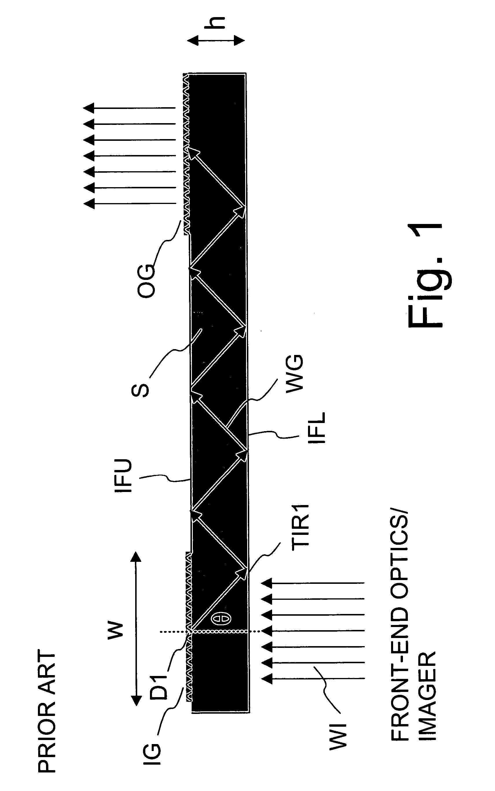
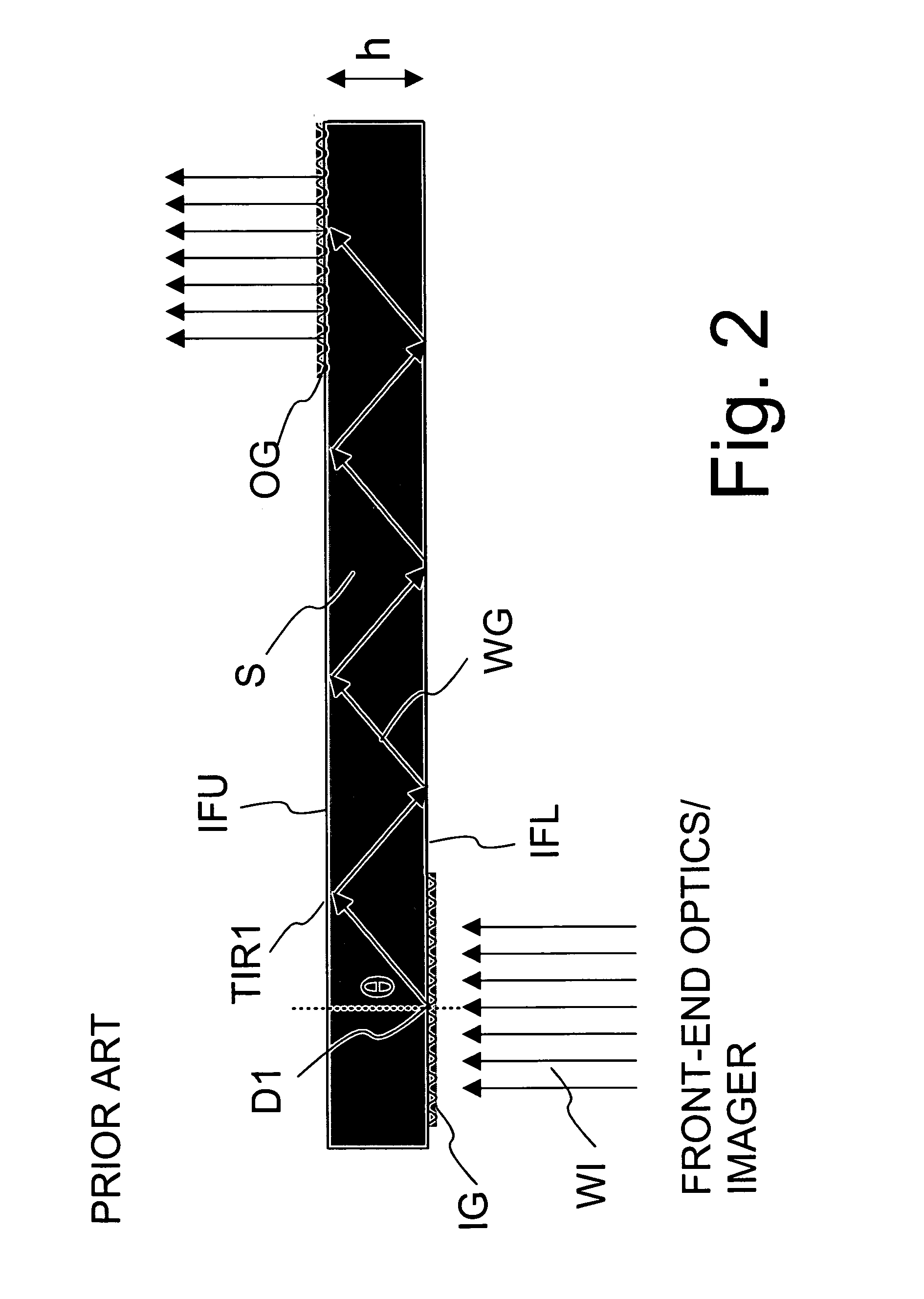
[0035]FIGS. 1 and 2, which present solutions known already from the related art, have already been discussed above.

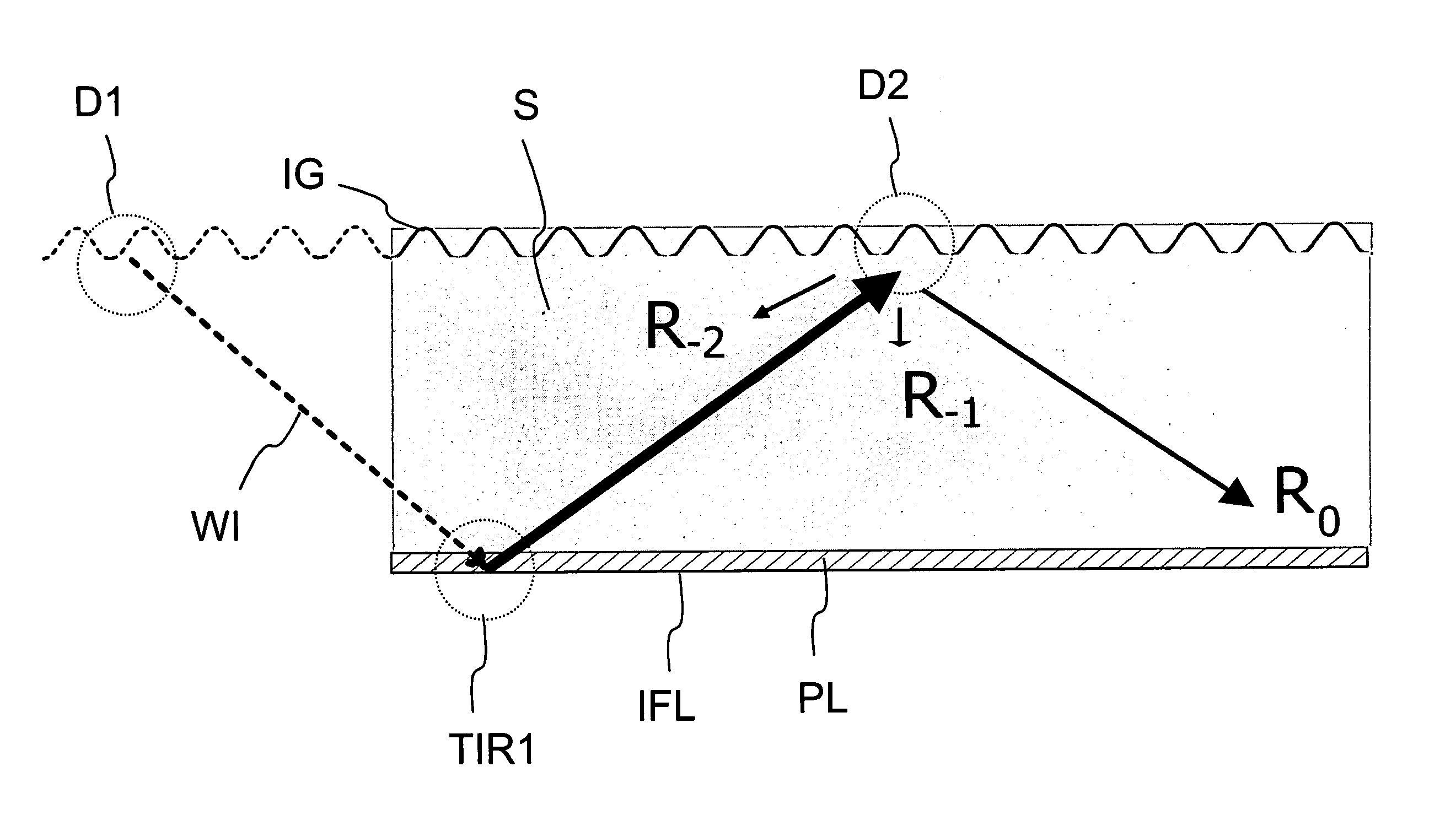
[0036]FIG. 3 illustrates schematically the second interaction / diffraction D2 of the light wave WI upon the in-coupling grating IG in a prior art type situation after the light wave has already experienced the first interaction / diffraction D1 and subsequent first TIR1.

[0037]In order to fulfil conditions for TIR and to keep the reflection angles modest, the refractive index of the substrate material S should be as high as possible. In this study a high refractive index plastic (n=1.71)...


PUM


Abstract

A method and optical system for coupling light from an incoming light wave (WI) into a waveguiding substrate (S) arranges the light wave (WI) to interact with a diffractive in-coupling grating element or elements (IG) arranged on or embedded within the substrate (S) and arranged to couple the energy from the light wave (WI) into a waveguided light wave (WG). The polarization state of the light wave (WI) is converted after its first interaction (D1) with the in-coupling grating element / elements (IG) and before a second interaction (D2) with the grating element / elements (IG) takes place. The method minimizes any “reverse” diffractions, which would direct light back towards the front-end optics and therefore to increase the width W of the in-coupling grating / gratings (IG). Preferred embodiments include diffractive beam expanders for virtual displays.

Description

CROSS REFERENCE TO RELATED APPLICATIONS[0001]This application claims priority under 35 USC §119 to Finnish Patent Application No. 20030715 filed on May 13, 2003.FIELD OF THE INVENTION[0002]The present invention relates to a method for coupling light into a planar waveguide. The invention also relates to an optical system for carrying out such a method.BACKGROUND OF THE INVENTION[0003]Generally speaking this invention relates to coupling of light into a planar waveguide, where preferably surface reliefs are used as in and out-coupling diffractive grating elements. Important applications include diffractive beam expanders for virtual displays, but the invention might also be applied to other optical imaging or illumination devices, where light needs to be coupled into a planar waveguide with high efficiency. Besides display systems, the invention may in its generic form be utilized in other type of optical systems as well, for example in optical couplers or other light modulator devic...

Claims


Application Information

Patent Timeline
Patent Type & Authority Patents(United States)
IPC IPC(8): G02B6/34G02B6/10G02B6/12G02B6/126
CPCG02B6/105G02B6/126G02B6/34G02B27/0081G02B6/29328G02B2006/12107
Inventor LEVOLA, TAPANI
Owner MAGIC LEAP INC
Why Eureka
Try Eureka