Developer supplying device, developing roller, developing device, image forming apparatus and process cartridge

a technology of developing rollers and developing devices, which is applied in the direction of electrographic process devices, instruments, optics, etc., can solve the problems of deterioration of the fluidity of the toner, decrease of the amount of charge in the toner, and agglomeration of toners, so as to achieve the effect of restraining mechanical stress

Inactive Publication Date: 2007-02-20
RICOH KK
View PDF27 Cites 9 Cited by
  • Summary
  • Abstract
  • Description
  • Claims
  • Application Information

AI Technical Summary

Benefits of technology

[0011]Because of these reasons, the present inventors recognized that a need exists for a developer supplying device, a developing roller, a developing device, an image forming apparatus, and a process cartridge that can obtain quality images over an extended period of time by restraining the mechanical stress on a developer when the toner is charged.
[0012]Accordingly, an object of the present invention is to hereby provide a developer supplying device, a developing roller, a developing device, an image forming apparatus, and a process cartridge that can obtain quality images over an extended period of time by restraining the mechanical stress on a developer when the toner is charged.

Problems solved by technology

These additives sink in the mother binder resin by the mechanical stress mentioned above, resulting in deterioration of the fluidity of the toner.
Therefore, the toner agglomerates and the amount of charge in the toner decreases, which has an adverse impact such as background fouling and poor toner supply.
In an image forming apparatus including the developing device using a single component developer mentioned above, the toner easily deteriorates and it is thus difficult to obtain images having good quality over an extended period of time.
Consequently, it is difficult to maintain the durability of the developing device over an extended period of time.
That is, the toner is abrasively charged by the rotation of the fur brush during transfer.
However, since the toner is transferred by the rotation of a fur brush, meaning that the toner is transferred with a mechanical stress, the toner possibly deteriorates due to the mechanical stress from the fur brush.

Method used


Image

  • Developer supplying device, developing roller, developing device, image forming apparatus and process cartridge
  • Developer supplying device, developing roller, developing device, image forming apparatus and process cartridge
  • Developer supplying device, developing roller, developing device, image forming apparatus and process cartridge

Examples


example 1

VARIANT EXAMPLE 1

[0074]Next, a Variant Example 1 is described. FIG. 8 is a diagram illustrating a developing device 40 of Variant Example 1. In the developing device 40, as illustrated in FIG. 8, a layer thickness regulating blade 407 is structured such that the layer thickness regulating blade 407 is in contact with the developing sleeve 404. This layer thickness regulating blade 407 is fixed to a holder (not shown) and has a free end having a length of from 10 to 15 mm. When the length of the free end of the layer thickness regulating blade 407 is too long, the developing device 40 increases in size. In contrast, when the length of the free end of the layer thickness regulating blade 407 is too short, the free end tends to vibrate when the free end contacts with the surface of the developing sleeve 404, resulting in occurrence of uneven stepping patterns on an image. It is preferred that the contact pressure of the layer thickness regulating blade 407 is from 0.049 to 2.45 Ncm. Wh...

example 2

VARIANT EXAMPLE 2

[0076]Next, a Variant Example 2 is described. FIG. 9 is a diagram illustrating the developing device 50 of this Example. The developing device 50 includes a fur brush 53 functioning as a charging member in its interior. The fur brush 53 abrasively charges a developer. The developing device 50 further includes a developing roller 51 and a layer thickness regulating member 58 in its casing. The layer thickness regulating member 58 is provided with a gap between the layer thickness regulating member 58 and the developing roller 51. As in the example described above, a suction bias by which the developer is electrostatically transferred from the inner circumference of a developing sleeve 52 to the outer circumference thereof is applied to the layer thickness regulating member 58. A developing roller 51 includes the developing sleeve 52 having the same structure as in the example described above, and the fur brush 53 functioning as a charging member disposed inside the d...

example 3

VARIANT EXAMPLE 3

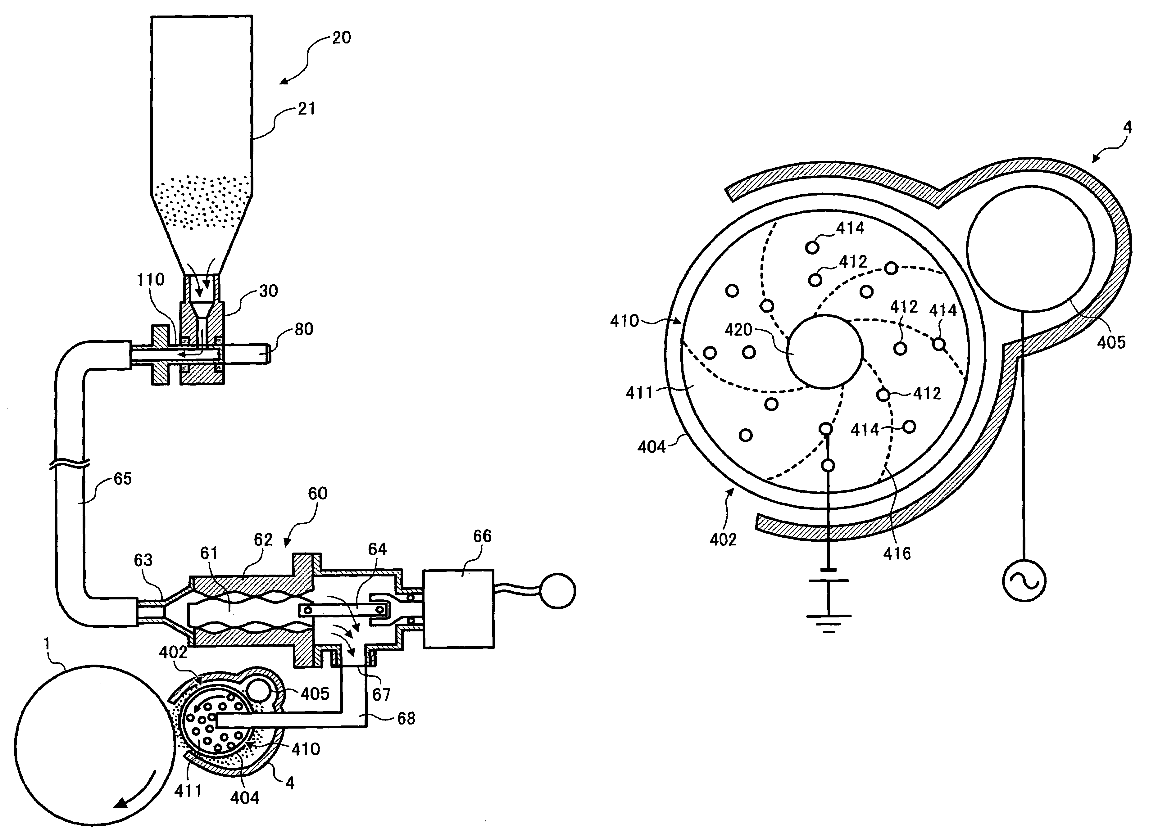
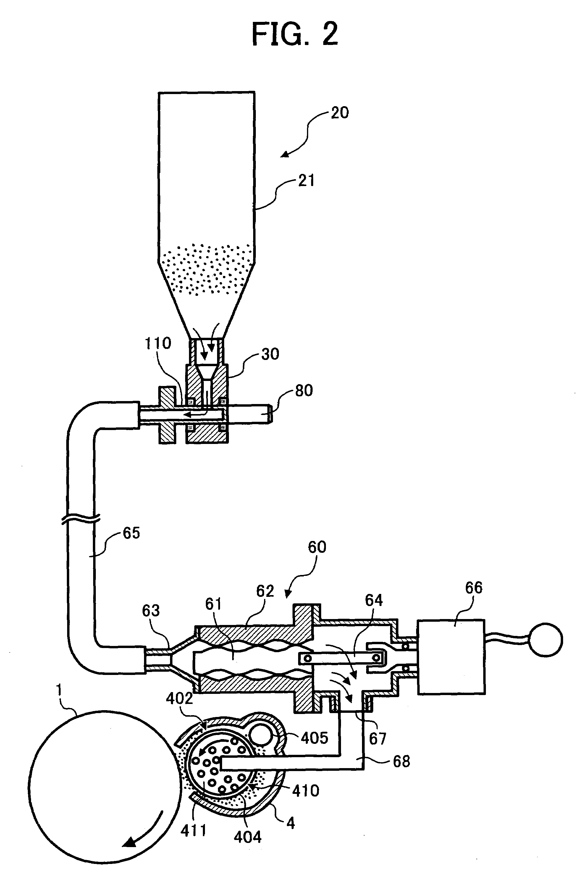
[0080]Next, a developing device 70 of a Variant Example 3 is described. FIG. 10 is a diagram illustrating the developing device 70 of Variant Example 3. In the developing device 70, a developer supplying member 73 functioning as a developer supplying system is externally provided to a developing roller 71. The developing device 70 includes the developing roller 71, a developer holding unit 75 holding a developer supplied from a developer replenishing system, and the developer supplying member 73 supplying the developer held in the developer holding unit 75 to the developing roller 71. The developer is replenished in the same manner as illustrated in FIG. 2. The developer supplying member 73 is disposed between the developing roller 71 and the developer holding unit 75. The developer supplying member 73 includes an open cell foam functioning as a charging member. The developer holding unit 75 includes first and second electroconductive plates 73a and 73b having a mes...


PUM


Abstract

A developer supplying device including a developer holding unit configured to hold a developer, a developer transfer device configured to electrostatically transfer the developer from the developer holding unit, and a charging member having holes piercing therethrough from the developer holding unit, to abrasively charge the developer by contacting the developer with walls of the holes while the developer is electrostatically transferred through the holes by the developer transfer device.

Description

BACKGROUND OF THE INVENTION[0001]1. Field of the Invention[0002]The present invention relates to a developer supplying device, a developing roller, a developing device, an image forming apparatus and a process cartridge.[0003]2. Discussion of the Background[0004]A developing device 200 illustrated in FIG. 14 has been used as a single component developer system using a single component developer. Such a single component developer contains a toner. This developing device 200 includes a developing roller 208 formed of an elastic body and a developer supplying roller 206, which is abrasively in contact with the developing roller 208, to supply a developer (i.e., toner) 204 thereto. In addition, the developing device 200 further includes a layer thickness regulating member 207, a developer holding unit 203 to hold the developer, and an agitator 205 functioning as an agitating member. The layer thickness regulating member 207 is in contact with the developing roller 208 to reduce the thic...

Claims


Application Information

Patent Timeline
Patent Type & Authority Patents(United States)
IPC IPC(8): G03G15/08
CPCG03G15/0805
Inventor AOKI, KATSUHIROOYAMA, HAJIMEIKEGUCHI, HIROSHIMIYOSHI, YASUOTAKAGAKI, HIROMITSU
Owner RICOH KK
Why Eureka
Try Eureka