Eureka AIR delivers breakthrough ideas for toughest innovation challenges, trusted by R&D personnel around the world.

Manufacturing method of heat-assisted magnetic head constituted of slider and light source unit

a technology of slider and light source unit, which is applied in the manufacture of head surfaces, special recording techniques, instruments, etc., can solve the problems of head not being able to write data to the magnetic stability of the record bit to be degraded, and the increase of the coercive force of the magnetic recording medium, so as to avoid excessive mechanical stress, facilitate the joining, and avoid the effect of excessive mechanical stress

Active Publication Date: 2011-11-29
TDK CORPARATION
View PDF12 Cites 10 Cited by
  • Summary
  • Abstract
  • Description
  • Claims
  • Application Information

AI Technical Summary

Benefits of technology

[0017]Therefore, an object of the present invention is to provide a manufacturing method of the heat-assisted magnetic recording head, in which the light source unit can be easily joined to the slider with sufficiently high accuracy of joining position, under avoiding the excessive mechanical stress applied to the light source.
[0034]In the above-described method for manufacturing the heat-assisted magnetic recording head, the laser diode emits light at the moment when the protruded portion of the lower surface of the laser diode begins to have a contact with the wall surface of the step; accordingly, the movement of the light source unit in the direction of arrow 83 (FIG. 10c) can be immediately stopped. Therefore, the laser diode can avoid suffering excessive mechanical stress. As a result, the light source unit can be easily joined to the slider with sufficiently high accuracy of joining position, under avoiding the excessive mechanical stress applied to the light source.
[0040]According to the above-described embodiment of manufacturing method, the positional alignment (the optical axis alignment) in the track width direction (Y-axis direction) as well as Z-axis direction, which is will be explained later, can be easily completed with sufficiently high positional accuracy in a mechanical manner, which excellently facilitates the joining of the light source unit and the slider.
[0045]According to the above-described embodiment of manufacturing method, the positional alignment (the optical axis alignment) in the track width direction (Y-axis direction) as well as Z-axis direction, which is will be explained later, can also be easily completed with sufficiently high positional accuracy in a mechanical manner, which excellently facilitates the joining of the light source unit and the slider.

Problems solved by technology

However, a problem is likely to occur that the decrease in size causes thermal stability of the magnetization of the record bit to be degraded.
However, the increase in energy KU causes the increase in coercive force of the magnetic recording medium.
Therefore, the head cannot write data to the magnetic recording medium when the coercive force of the medium exceeds the write field limit.
As a result, a problem that mass-production efficiency of the head is significantly degraded may be likely to occur.
Further, on joining the light source unit to the slider, there is a possibility that, when the light source, for example, a laser diode, contacts with the back surface of the slider, the generated mechanical stress is applied to the laser diode, which may cause the laser diode to be damaged.

Method used


Image

  • Manufacturing method of heat-assisted magnetic head constituted of slider and light source unit
  • Manufacturing method of heat-assisted magnetic head constituted of slider and light source unit
  • Manufacturing method of heat-assisted magnetic head constituted of slider and light source unit

Examples


Embodiment Construction

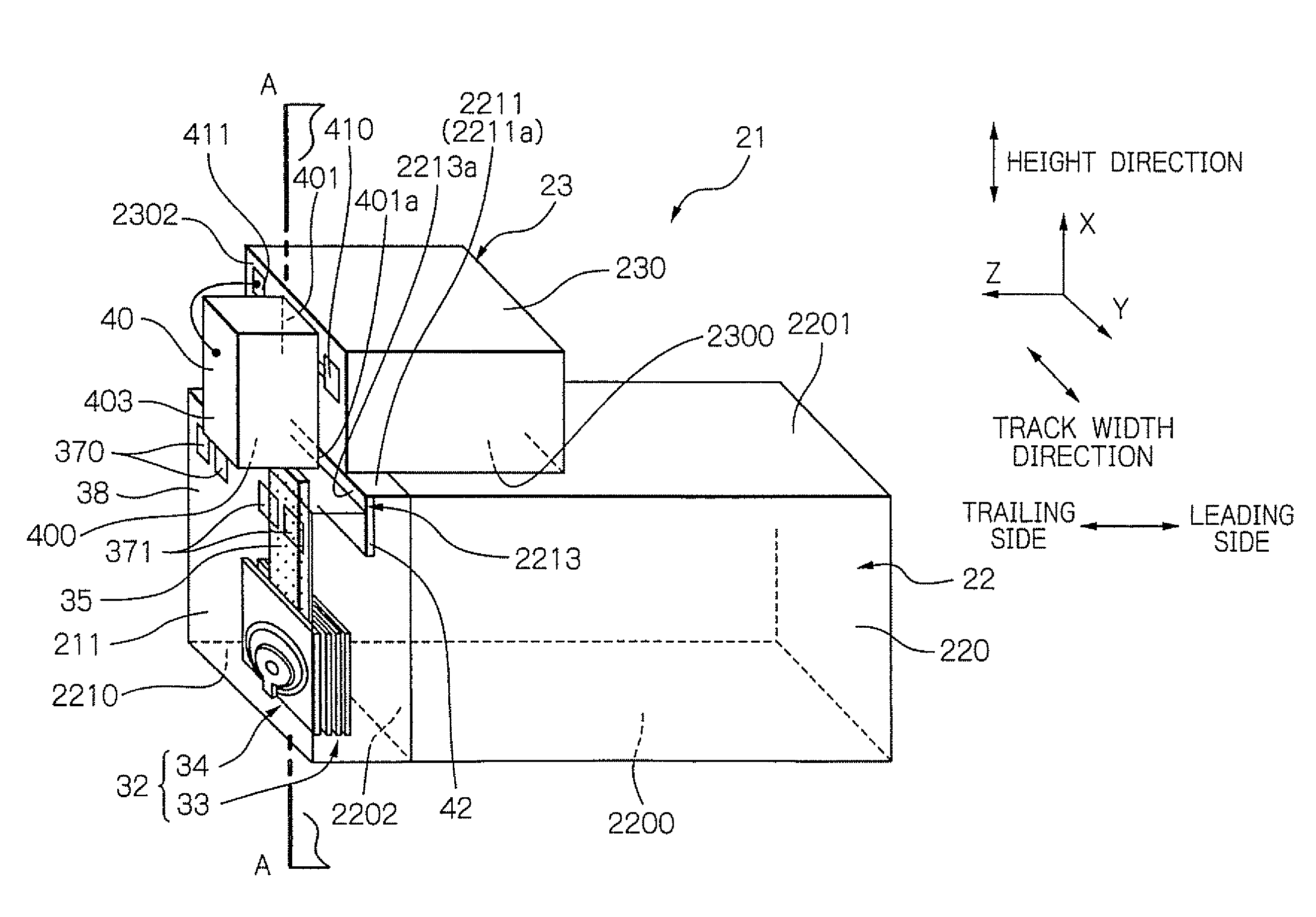
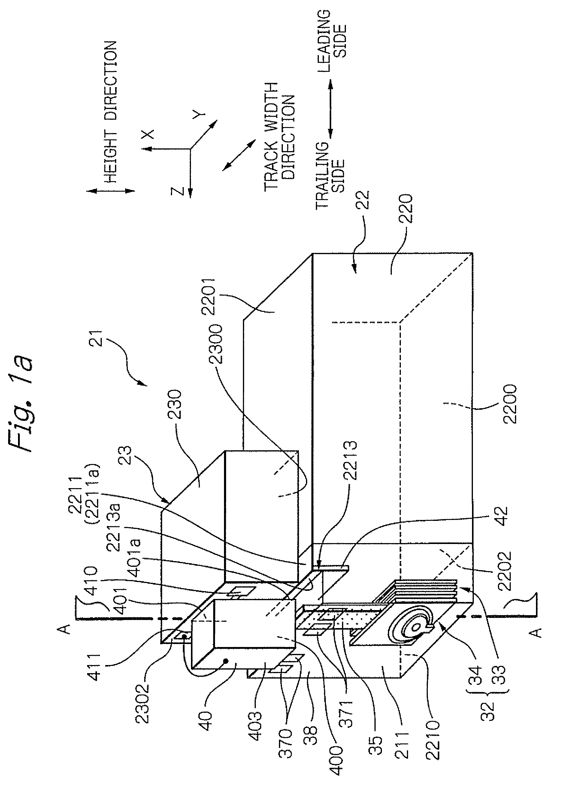
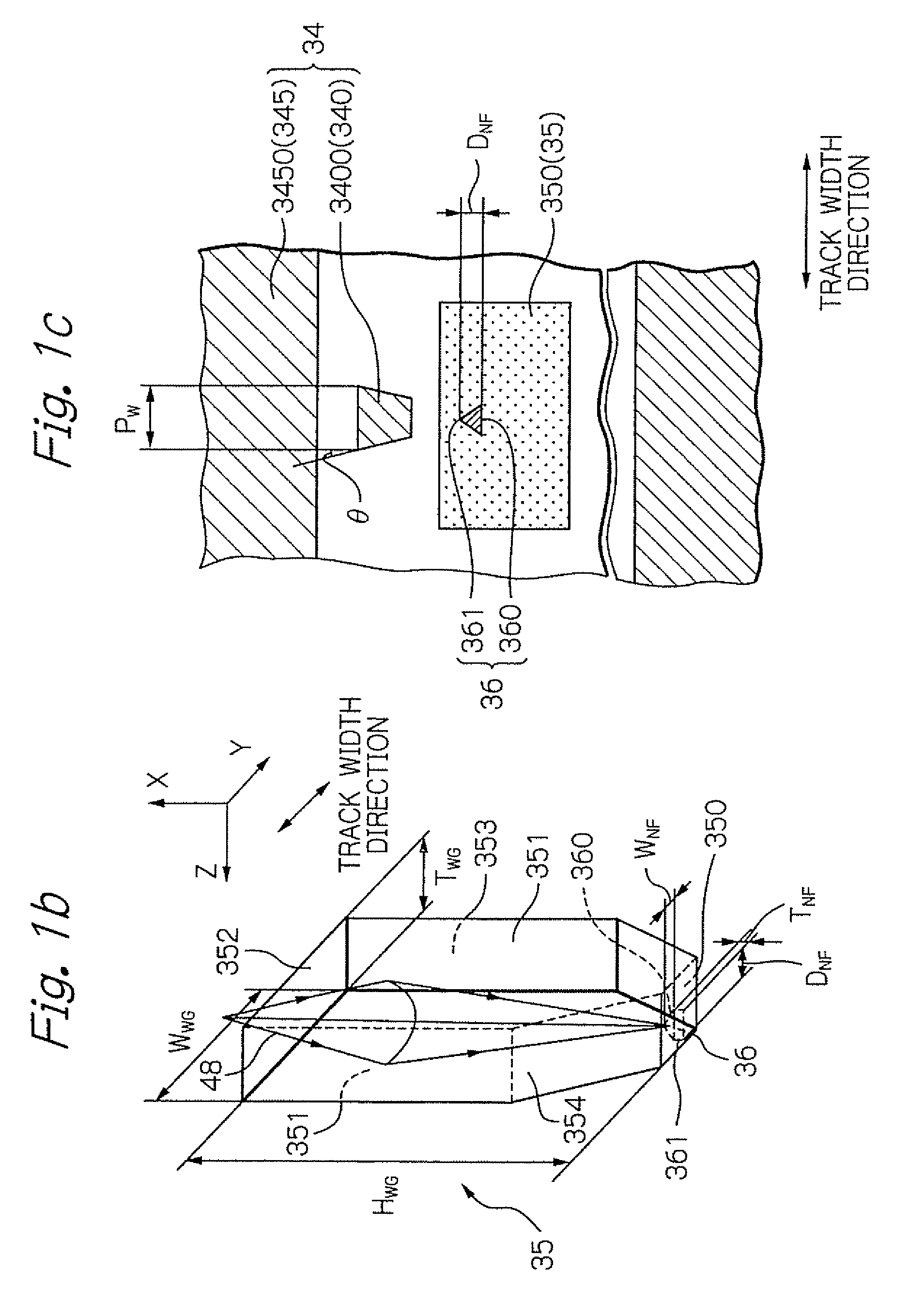
[0061]FIG. 1a shows a perspective view illustrating one embodiment of a heat-assisted magnetic recording head manufactured by the manufacturing method according to the present invention. FIG. 1b shows a perspective view illustrating one embodiment of waveguide 35 and near-field light generating element 36. Further, FIG. 1c shows a plain view illustrating the shapes on the head-part end surface 2210 of the ends of electromagnetic transducer 34, waveguide 35 and near-field light generating element 36.

(Heat-Assisted Magnetic Recording Head)

[0062]As shown in FIG. 1a, a heat-assisted magnetic recording head 21 is constituted by joining the light source unit 23, which includes a laser diode 40 as a light source, to the slider 22 that includes: a waveguide 35 for guiding laser light generated from the laser diode 40 to the medium-opposed surface side; and the near-field light generating element 36 for generating near-field light by receiving the laser light.

[0063]The slider 22 includes: a ...


PUM

PropertyMeasurementUnit
distanceaaaaaaaaaa
height HWGaaaaaaaaaa

Abstract

Provided is a manufacturing method of heat-assisted magnetic recording head, in which a light source unit can be easily joined to a slider with sufficiently high accuracy, under avoiding the excessive mechanical stress. The manufacturing method comprises the steps of: moving relatively the light source unit and the slider, while applying a sufficient voltage between an upper electrode of the light source and an electrode layer provided in the slider; and setting the light source unit and the slider in desired positions in a direction perpendicular to the element-integration surface of the slider substrate. The desired positions are positions where the light source just emits due to a surface contact between: the protruded portion of the lower surface of the light source; and the upper surface of the electrode layer, which is a portion of the wall surface of a step formed on the head part.

Description

BACKGROUND OF THE INVENTION[0001]1. Field of the Invention[0002]The present invention relates to a method for manufacturing a magnetic head for writing data signals according to a heat-assisted magnetic recording technique.[0003]2. Description of the Related Art[0004]In a magnetic disk drive apparatus intended for higher recording density, a thin-film magnetic head within it needs to be further improved in its performance. As such a thin-film magnetic head, a composite-type thin-film magnetic head is widely used, which has a stacked structure of a magnetoresistive (MR) element for reading data signals and an electromagnetic transducer for writing data signals.[0005]Generally, a magnetic recording medium is magnetically discontinuous, in which magnetic microparticles are gathered together. Usually, each of the magnetic microparticles has a single magnetic-domain structure; and in the medium, one record bit consists of a plurality of the magnetic microparticles. Therefore, for improvi...

Claims


Application Information

Patent Timeline
Patent Type & Authority Patents(United States)
IPC IPC(8): G11B5/127H04R31/00
CPCG11B5/102G11B5/314G11B5/3163G11B2005/0005G11B2005/0021Y10T156/1062Y10T29/49025Y10T29/49052Y10T29/49043Y10T29/49044Y10T29/49041Y10T29/49046
Inventor SHIMAZAWA, KOJIITO, YASUHIROKOMURA, EIJITAKAYAMA, SEIICHITANAKA, KOSUKE
Owner TDK CORPARATION
Why Eureka
Eureka Blog
Learn More