Laser measurement system

a laser measurement and laser technology, applied in the direction of mechanical measurement arrangements, instruments, and reradiation, etc., can solve the problems of complicated scanning arrangement used in the above arrangemen

Active Publication Date: 2007-02-27
ADVANCED MEASUREMENT SYST INC +1
View PDF11 Cites 39 Cited by
  • Summary
  • Abstract
  • Description
  • Claims
  • Application Information

AI Technical Summary

Benefits of technology

[0014]Yet another advantageous feature of the laser measurement system of the present invention is that it compares the undamaged or as-built information for the vehicle frame to be repaired with the measured configuration of the damaged vehicle frame by allowing the technician to select the as-built frame information for the vehicle to be repaired, observe the vehicle's actual state as measured by the laser measurement system and determine the difference between the as-built and actual state of the frame, project the r

Problems solved by technology

The scanning arrangement used in the above arrangement is complicated, requiring the use of rotati

Method used


Image

  • Laser measurement system
  • Laser measurement system
  • Laser measurement system

Examples


Embodiment Construction

)

The Laser Measurement System

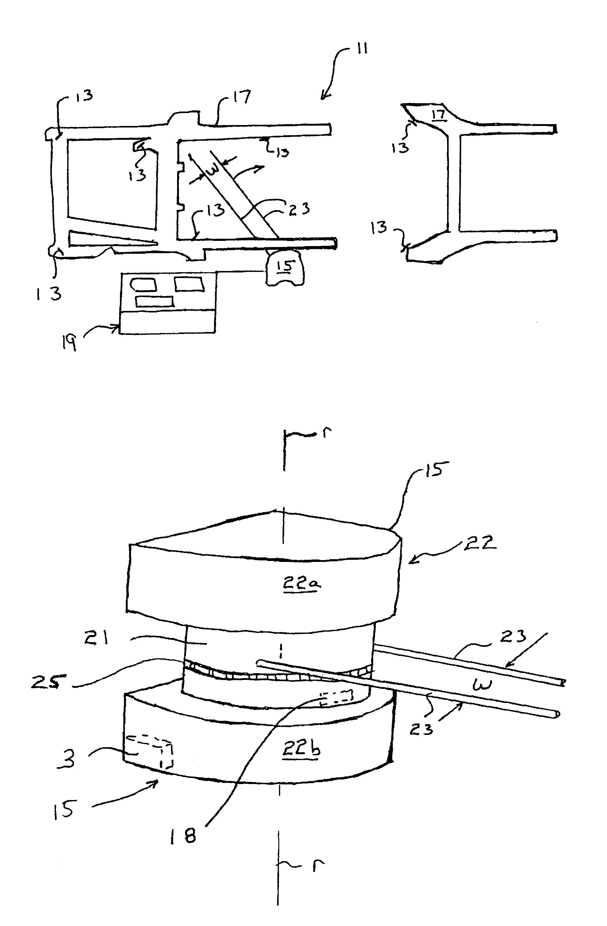
[0031]Referring to FIG. 1, one embodiment of a laser measurement system, generally indicated at 11, is shown in accordance with the teaching of the present invention for use, for example, in automotive collision repairs of a vehicle frame 17. The system 11 comprises three primary elements: a rotating laser transmitter / scanner 15, a plurality of electronic optical detector elements or active targets 13 that are attached to frame 17 and detect optical emissions from the laser scanner to develop position information for the frame 17 to be repaired and a host computer, generally shown at 19, with software to display and compare position data received from the active targets 13 with stored reference data delineating the optimal or “as-built” configuration of the frame 17 so as to display a simulated model of the frame of the vehicle showing the difference between as-built configuration and the actual configuration of the vehicle frame in three dimensions.

[003...


PUM


Abstract

A laser measurement system indicates the difference between an actual position of a vehicle frame reference point on a vehicle frame and a normal position employing a rotating laser scanner; an electro-optical detector and a host computer. A positioning arrangement is also provided for positioning the electro-optical detector at a known distance from the reference point. In operation, the host computer queries the scanner and detector via a communication link, calculates the actual position of the reference point, and displays the difference between the position of the vehicle reference point on the vehicle frame and the normal position.

Description

BACKGROUND OF THE INVENTION[0001]1. Field of the Invention[0002]This invention generally relates a laser measurement system for determining the location of active targets in three-dimensional space, and more particularly to a laser measurement system for determining deformation in vehicle bodies for automobile collision repair using a laser scanning apparatus in conjunction with a plurality of active targets suspended from known reference points on the vehicle to calculate three dimensional spatial coordinates defining the actual positions of the active targets which is then compared with manufacturer-provided specification values to determine the extent of deformation of the vehicle body.[0003]2. Background of the Invention[0004]Vehicle frame deformation measurement systems, such as disclosed by U.S. Pat. Nos. 4,997,283, 5,251,013 and 5,801,834, use a pair of rotating laser light beams emitted from a laser measuring unit, however, these measurement systems scan passive reflective t...

Claims


Application Information

Patent Timeline
IPC IPC(8): G01C5/00
CPCG01B5/0025G01C15/002G01C15/006G01S3/789G01S11/12G01S1/70Y10S33/21G01S7/003
Inventor HANCHETT, MICHAEL T.KOOP, DARRYL W.LAWTON, ROY E.HARTL, JIM C.KNOKE, ROBIN L.
Owner ADVANCED MEASUREMENT SYST INC
Why Eureka
Try Eureka