Plunger type master cylinder

a master cylinder, a technology of a cylinder head and a master cylinder head, applied in the direction of rotary clutches, fluid couplings, brake systems, etc., to achieve the effect of reducing the number of component parts and high precision

Inactive Publication Date: 2007-02-27
BOSCH CORP
View PDF14 Cites 29 Cited by
  • Summary
  • Abstract
  • Description
  • Claims
  • Application Information

AI Technical Summary

Benefits of technology

[0014]Owing to the recess formed in the outer periphery of the piston under feature 1, and the seal coupling part of the seal ring and the void between the inner periphery of the inner lip and the outer peripheral wall surface of the piston under feature 2, the fluid pressure chamber can be communicated with the reservoir side when the master cylinder is in a non-operating position. Owing to the unique and characteristic arrangement of the seal coupling part (or the distal end part of the inner lip of the seal ring) when the master cylinder is in a non-operating position under feature 3, durability of the seal ring can be enhanced and invalid stroke can be reduced. Particularly, those features 1 through 3 are of great help to solve three problems without impairing the features which others have and by mutually cooperating.
[0015]Particularly, the distal end part of the inner lip of the seal ring is located in the opening of the relief port when the master cylinder is in a non-operating position. This means that the seal coupling part of the seal ring traverses only the edge on the side of the first edge of all the entire edge of the opening of the relief port in accordance with non-operation and operation of the master cylinder. Therefore, the repeat of non-operation and operation reduces the number of times for the seal coupling part to traverse the edge into a half. It can be expected that durability of the seal ring is enhanced to that extent.
[0017]The recess formed at the outer periphery of the piston ranges over the entire length in the peripheral direction of the piston but it ranges in a limited region in the vicinity of the relief port in the axial direction. Thus, the piston has enlarged-diameter parts which are each located in a front and a rear position of the recess. In a preferred embodiment, the both front and rear parts of the recess of the piston are guided by a piston guide part on the cylinder housing side. In case the piston guide part is arranged at the front side of the recess, the sealing force in the peripheral direction of the seal ring can effectively be uniformed because the piston guide part is in a position near the seal coupling part of the seal ring which is brought into the opening of the seal ring.
[0021]As a modified embodiment having the feature 4, the second projection parts are provided parallel to the first projection parts (projection parts are provided in two row between the root part and the seal coupling part). Owing to this arrangement, the void on the inner periphery side of the inner lip can more surely be obtained. Although the features 4 and 5 can individually effectively act in obtaining fluid supply property, an embodiment having both the features 4 and 5 is more preferable.
[0022]In the master cylinder of this invention, it is accepted that in order to attach the seal ring to the cylinder housing side, a slide ring is inserted in the inner periphery of the cylinder bore and one side of the seal ring is supported by one end of the slide ring. It is more preferable that an attachment groove for attaching the seal ring is provided directly to the inner peripheral wall surface of the cylinder bore of the cylinder housing. Owing to this arrangement, the number of component parts can be reduced, and the positional relation between the relief port on the piston side and the seal ring on the cylinder housing side can established with higher precision. The seal ring is disposed in the attachment groove with its base part sunk in the attachment groove and with the seal coupling part on the inner periphery of the distal end part of the inner peripheral lip allowed to project outward from the attachment groove.

Problems solved by technology

As technical problems to be solved for such a plunger type master cylinder, firstly, there is such a problem as how to reduce the invalid stroke caused by braking operation and secondly, there is such a problem as how to prevent the residue of a brake fluid pressure (so-called residual pressure) in a fluid pressure chamber during non-operation of the brake.

Method used


Image

  • Plunger type master cylinder
  • Plunger type master cylinder
  • Plunger type master cylinder

Examples


Embodiment Construction

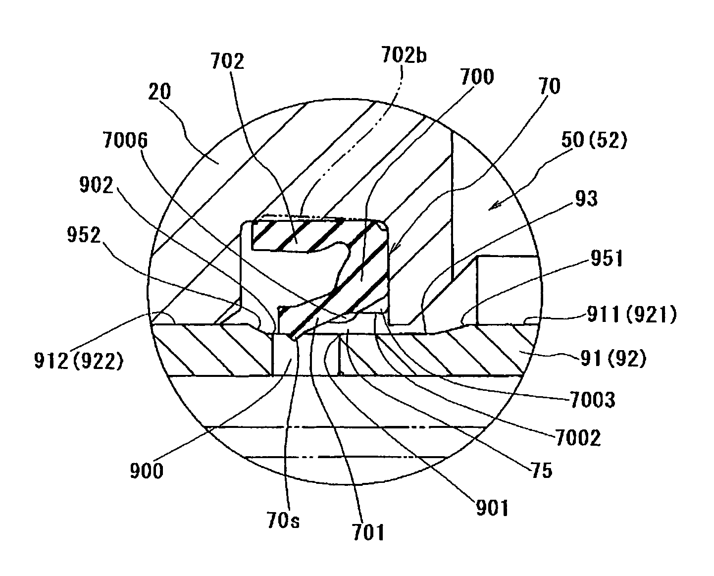
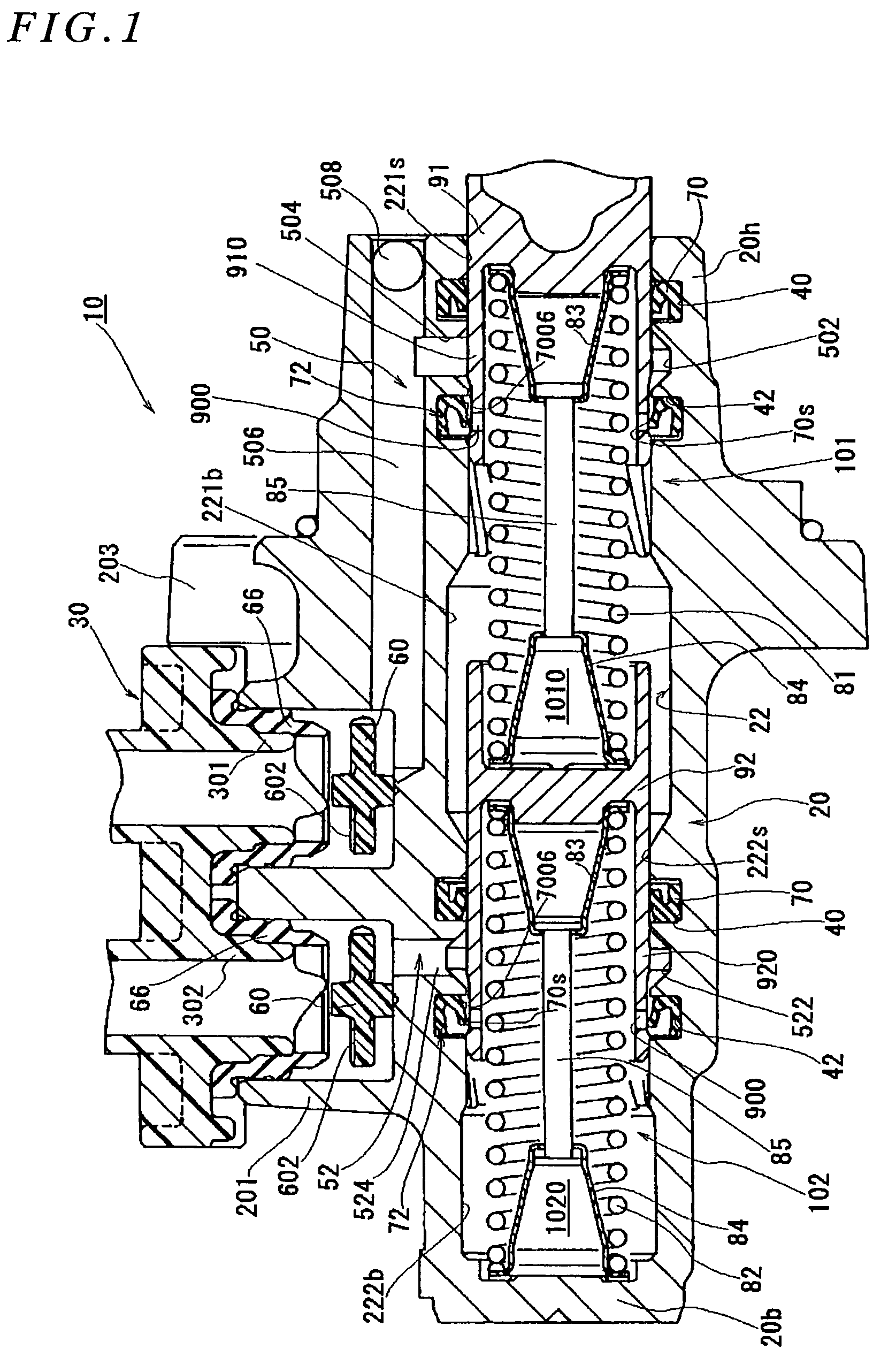
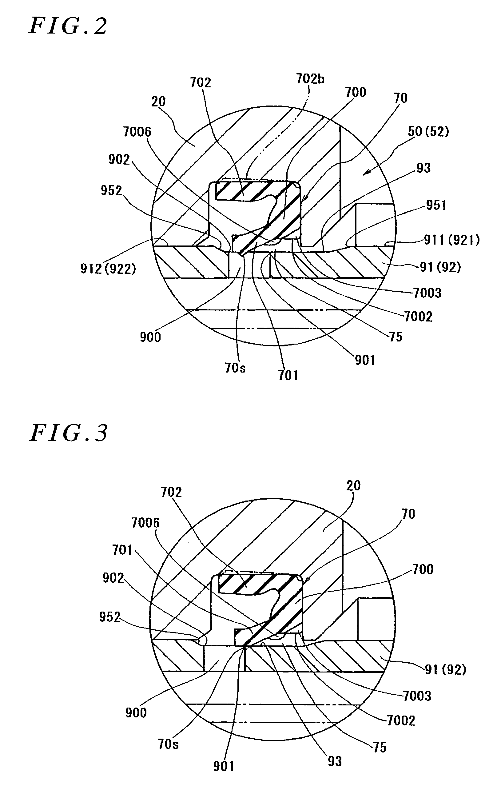
[0034]FIG. 1 is one embodiment of a tandem plunger type master cylinder to which the present invention is applied. The tandem master cylinder 10 comprises a primary part 101 and a secondary part 102 which are mutually independent. In the illustrated embodiment, the way of thinking according to the present invention is applied to those two parts 101, 102.

[0035]First, referring to FIG. 1, an overall construction of the tandem master cylinder 10 is made manifest. An outer shell of the master cylinder 10 is a cylinder housing 20 made of an aluminum alloy. The cylinder housing 20 is provided at an upper part thereof with a boss part 201 for supporting a reservoir 30 and at its inside with a cylinder bore 22 axially extending from a first end part 20h which is open, to a second end part 20b which is closed. The boss part 201 is a part for supporting the reservoir 30 which reserves therein working fluid. Nipples 301, 302 of the reservoir 30 are fitted for connection to the inner side of th...


PUM


Abstract

To provide a plunger type master cylinder capable of reducing invalid stroke and preventing residual pressure without impairing durability of a seal ling (70). A piston (91) of the master cylinder has a recess (93) at its outer peripheral surface and a relief port (900) in its recess (93). The seal ring (70) has a seal coupling part (70s) on the inner periphery of the distal end part of an inner peripheral lip (701). The seal coupling part (70s) is located at the opening of the relief portion (900) on the piston (91) side when the brake is in a non-operating position. The distance between said seal coupling part (70s) and said relief port (900) is short. The seal ring (70) additionally has first and second projection parts (7006, 7002) on the inner peripheral surface of the inner peripheral lip (701). By this, a flow passage for working fluid can be obtained on the inner periphery side of the inner peripheral lip (701).

Description

[0001]This application is a 371 of PCT / JP2004 / 005725 filed on Apr. 21, 2004, published on Nov. 4, 2004 under publication number WO 2004 / 094208 A1 which claims priority benefits from Japanese Patent Application Number 2003-118943 filed Apr. 23, 2003 and Japanese Patent Application Number 2003-118944 filed Apr. 23, 2003 and Japanese Patent Application Number 2003-118945 filed Apr. 23, 2003.TECHNICAL FIELD[0002]This invention relates to a plunger type master cylinder used in a hydraulic brake system for vehicles, and the like, and more particularly to the technique of a master cylinder suited for brake control (for example, automatic brake control for controlling the attitude of a vehicle, or traction control for controlling the braking force of a drive wheel at the time of acceleration of a vehicle, and the like) which is performed separately from the manual brake control made by a driver.BACKGROUND ART[0003]A plunger type master cylinder used for the purposes as mentioned above has a...

Claims


Application Information

Patent Timeline
Patent Type & Authority Patents(United States)
IPC IPC(8): B60T11/236B60T11/20B60T11/232
CPCB60T11/236B60T11/232
Inventor ISHIKAWA, KAZUYOSHIISHIWATA, ICHIROTAIRA, KAZUHISAMASUDA, TETSUYAMIYAHARA, MINORUYANAGI, KUNIO
Owner BOSCH CORP
Why Eureka
Try Eureka