Sealing ring

a sealing ring and sealing technology, applied in the field of sealing ring, can solve the problems of wear to the wear profiled element, and achieve the effect of increasing the flexibility of the sealing ring and facilitating installation

Active Publication Date: 2020-02-11
KRONES AG
View PDF22 Cites 0 Cited by
  • Summary
  • Abstract
  • Description
  • Claims
  • Application Information

AI Technical Summary

Benefits of technology

[0012]Due to the fact that the seal main body has at least one region of reduced radius in order to facilitate the deformation of the seal main body during assembly, it is also possible to insert the sealing ring in closed housing grooves, obviating the need to open the housing groove to enable this. This is particularly important when a multiplicity of such sealing rings are inserted in a rotary media distributor, since by this means the effort and expense required to exchange the sealing rings can be reduced, and one or a plurality of sealing rings can be installed in a housing, thereby making it possible to reduce the downtimes of a beverage filling plant.
[0026]In an embodiment, such a protruding element is provided for each region of reduced radius, so that the sealing ring main body, when inserted in the housing groove, fully contacts and is supported by the housing groove in a radial direction. In this manner a highly reliable anti-rotation element can also be provided, which when under load does not result in an elongation of the material or an elastic displacement of the sealing ring. By this means the durability of the sealing ring can be improved.

Problems solved by technology

The wear profiled element thus absorbs the relative movement between the sealing ring and the stationary machine shaft, with the result that wear occurs to the wear profiled element only.

Method used


Image

  • Sealing ring
  • Sealing ring

Examples


Embodiment Construction

[0033]Examples of embodiments are described below with the aid of the figures. In the figures, elements which are identical or similar, or have identical effects, are designated with identical reference signs. In order to avoid redundancy, repeated description of these elements is in part dispensed with in the description below.

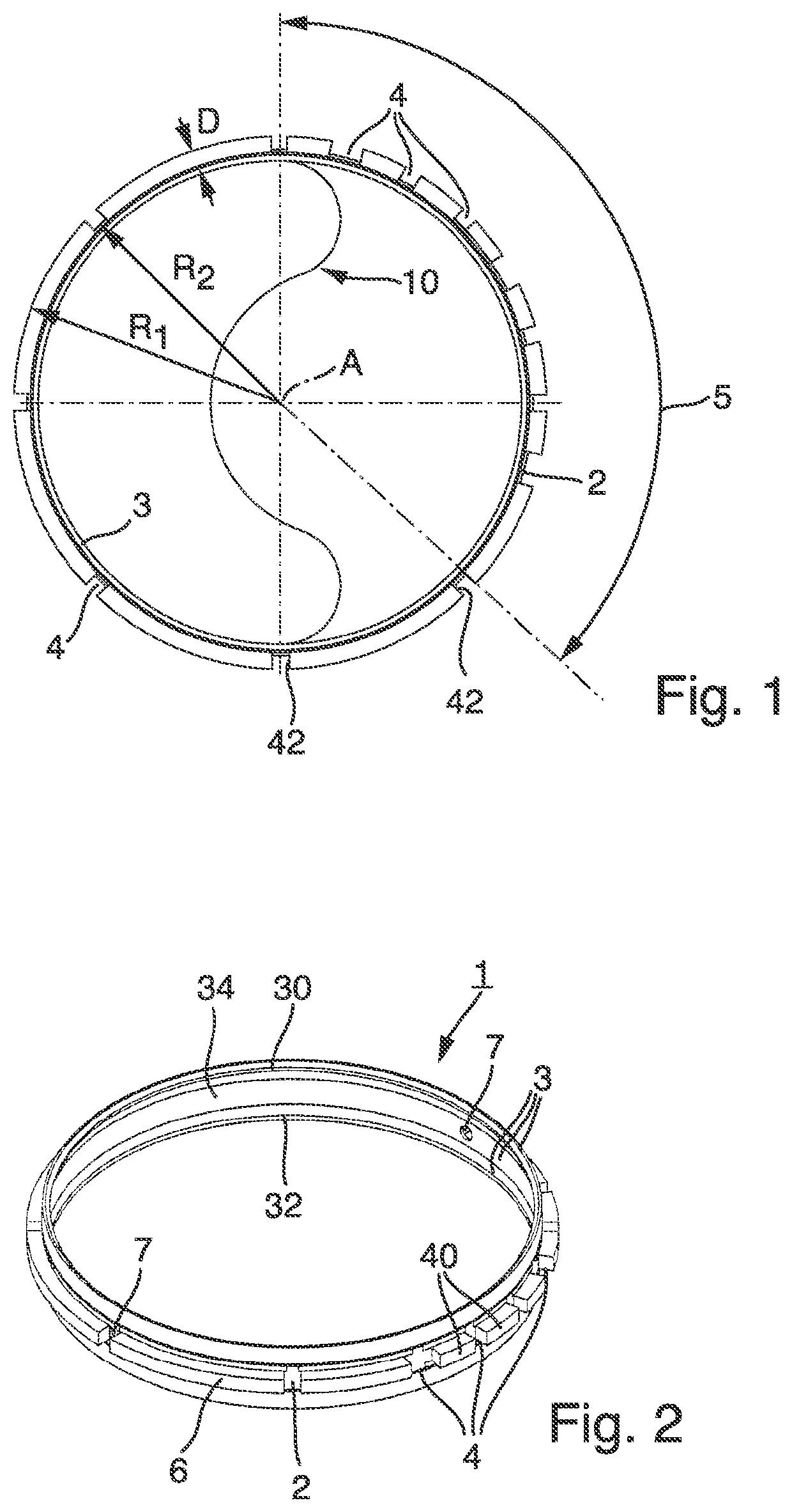
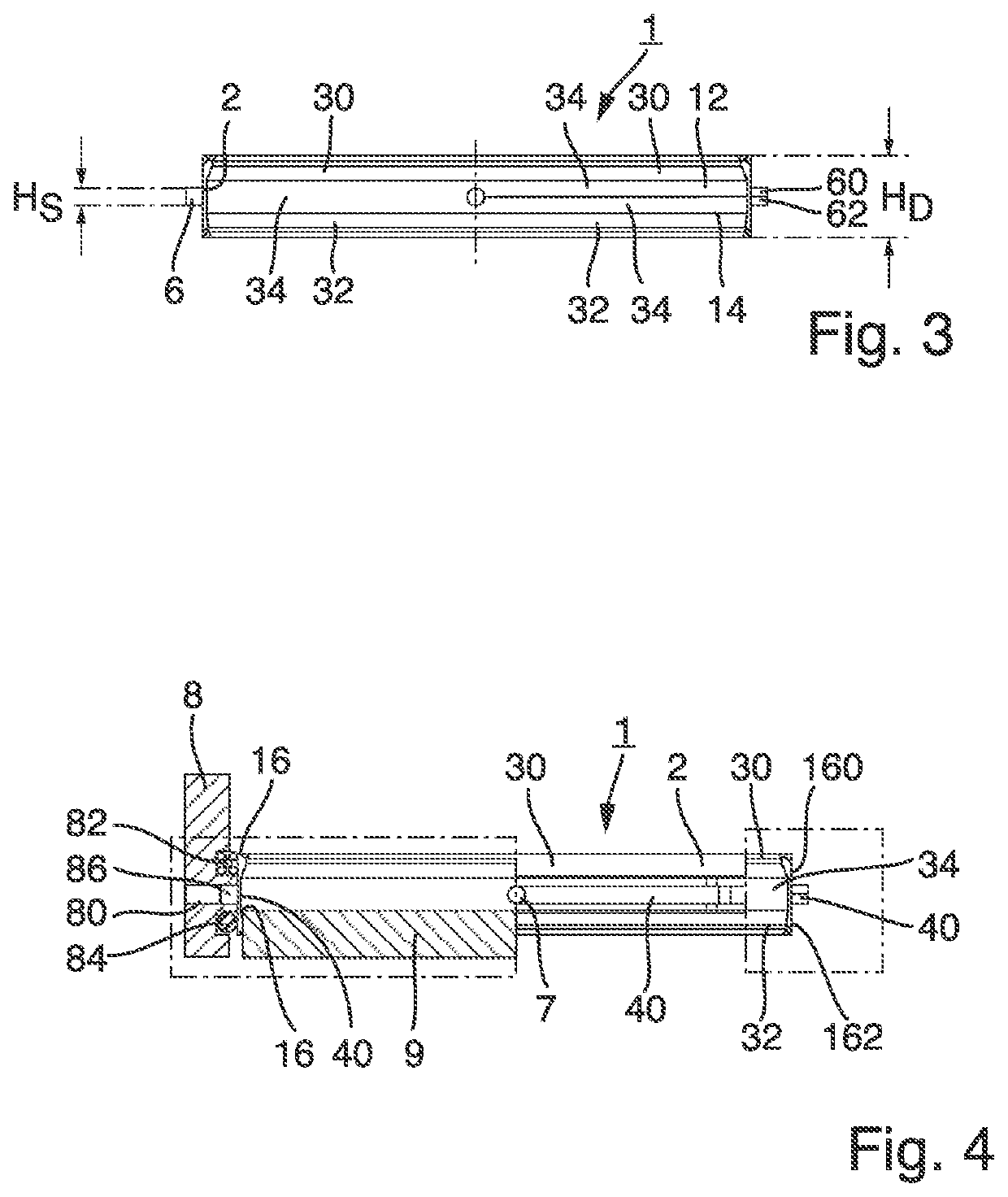
[0034]FIGS. 1 to 3 show a schematic plan view, a schematic side elevation and a schematic perspective view of a sealing ring 1 in an example embodiment. The sealing ring 1 has an annular seal main body 2, and a wear profiled element 3 arranged radially within the seal main body 2. The seal main body 2 is designed to retain the wear profiled element 3 and apply a radial pretensioning force to the wear profiled element 3. The seal main body 2 is in several embodiments elastic, in order that it can apply the pretensioning force and in order to ensure that the sealing ring 1 is reliably held in tension between the components that are to be sealed relative to each...


PUM


Abstract

A sealing ring for sealing a second component, which rotates in relation to a first component, for example for sealing a distribution channel of a rotary media distributor in a beverage filling system is described. The sealing ring includes an annular seal main body to be accommodated on the first component and a wear profiled element arranged radially within the seal main body for contacting the second component in a sealing manner, wherein the seal main body has at least one region of reduced radius in order to enable deformation of the seal main body as the seal main body is assembled with the first component.

Description

CROSS REFERENCE TO RELATED APPLICATIONS[0001]This application is a national stage of International Application No. PCT / EP2016 / 050279, filed Jan. 8, 2016, which claims priority from German Patent Application No. 20 2015 100 048.0 filed on Jan. 8, 2015 in the German Patent and Trademark Office, the disclosures of which are incorporated herein by reference in their entirety.BACKGROUNDTechnical Field[0002]The present invention relates to a sealing ring for sealing a second component, which rotates in relation to a first component, for example, for sealing a distribution channel of a rotary media distributor in a beverage filling plant.Related Art[0003]With rotary machines in the field of beverage filling, for example with rotary fillers, rotary sterilizers or rotary rinsers, it is necessary to transfer fluid from stationary components of the plant, for example a machine frame, to components of the plant that rotate relative to the stationary components of the plant. This is for example ...

Claims


Application Information

Patent Timeline
Patent Type & Authority Patents(United States)
IPC IPC(8): F16J15/3284F16J15/3268
CPCF16J15/3284F16J15/3268
Inventor BRAUN, FRANZSCHWARZFISCHER, PETER
Owner KRONES AG
Why Eureka
Try Eureka