
Line work tool and method thereof

a work tool and work method technology, applied in the field of line work tools, can solve the problems of increasing the difficulty and danger of such jobs, affecting the operation of the tool, so as to facilitate the manipulation of high-voltage connections, easy and secure engagement of the switch barrel or the ring, effect of facilitating the effect of high-voltage connection

Inactive Publication Date: 2007-02-27
RIDER JACK H
View PDF49 Cites 14 Cited by
  • Summary
  • Abstract
  • Description
  • Claims
  • Application Information

AI Technical Summary

Benefits of technology

"The present invention is a line work tool device and method that provides assistance in positioning and interacting with a target workpiece, such as a high voltage switch. The device includes a central body with a mount structure for easy use on a hot stick, and a ring engagement member that facilitates access to the switch barrel. The device also has a cutout receiving port and a unique inverted \"L\" shaped member that helps guide the tool in interacting with the switch. The device can perform multiple functions, including delivery of pushing and pulling forces, and can be used in manipulating tree branches and hanging lines. It is easy to use, secure, and can perform safely regardless of weather and visibility conditions."

Problems solved by technology

Unfortunately, these procedures must often be performed in stormy and / or windy conditions; and poor environmental circumstances usually serve to increase the difficulty and danger of such jobs.
That is, in order to disconnect a typical barrel switch, a small ring must be engaged by the lineman, oftentimes from a position some thirty or forty feet below, wherein a physical pulling force then serves to uncouple the switch components, disrupting the flow of power.
In rainy or other conditions that inhibit visibility, and / or under windy conditions, such exacting positioning is difficult, if not impossible.

Method used


Image

  • Line work tool and method thereof
  • Line work tool and method thereof
  • Line work tool and method thereof

Examples


Embodiment Construction

[0030]In describing the preferred and alternate embodiments of the present invention, as illustrated in the figures and / or described herein, specific terminology is employed for the sake of clarity. The invention, however, is not intended to be limited to the specific terminology so selected, and it is to be understood that each specific element includes all technical equivalents that operate in a similar manner to accomplish similar functions.

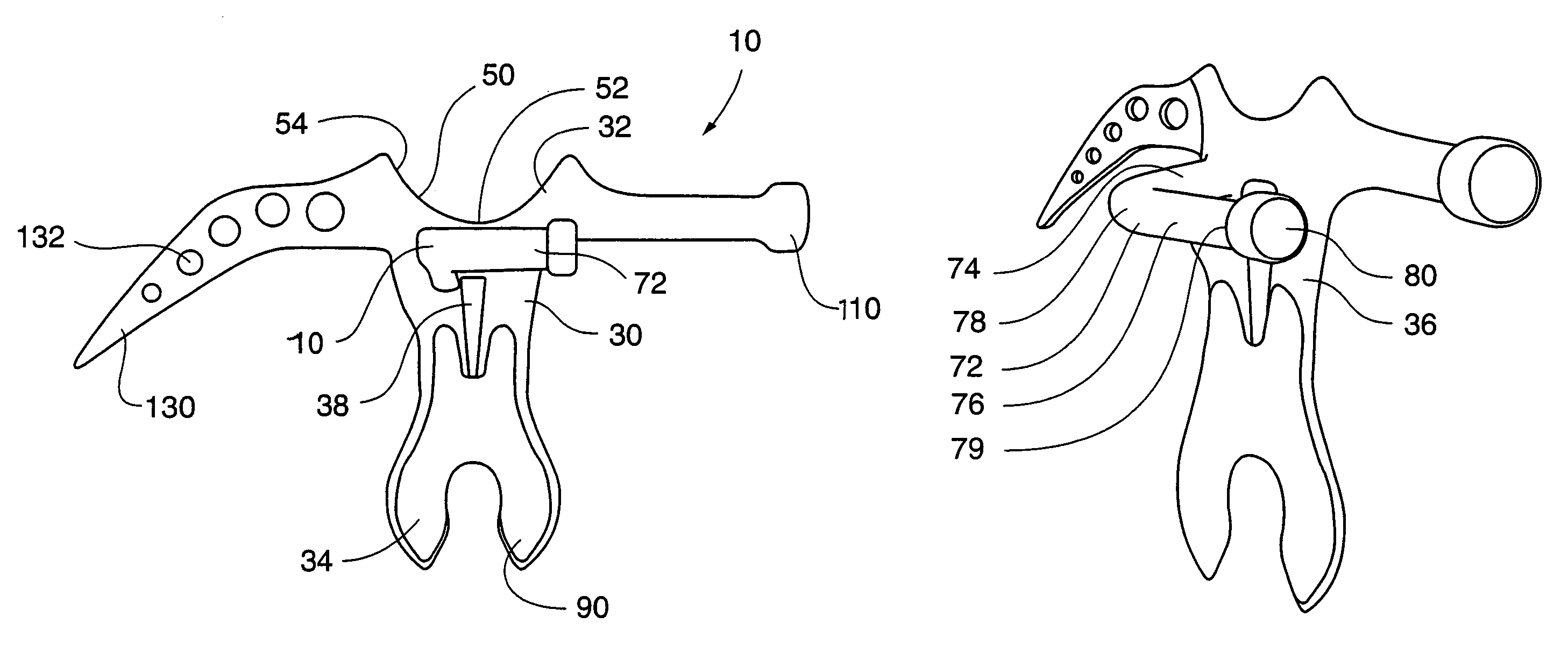
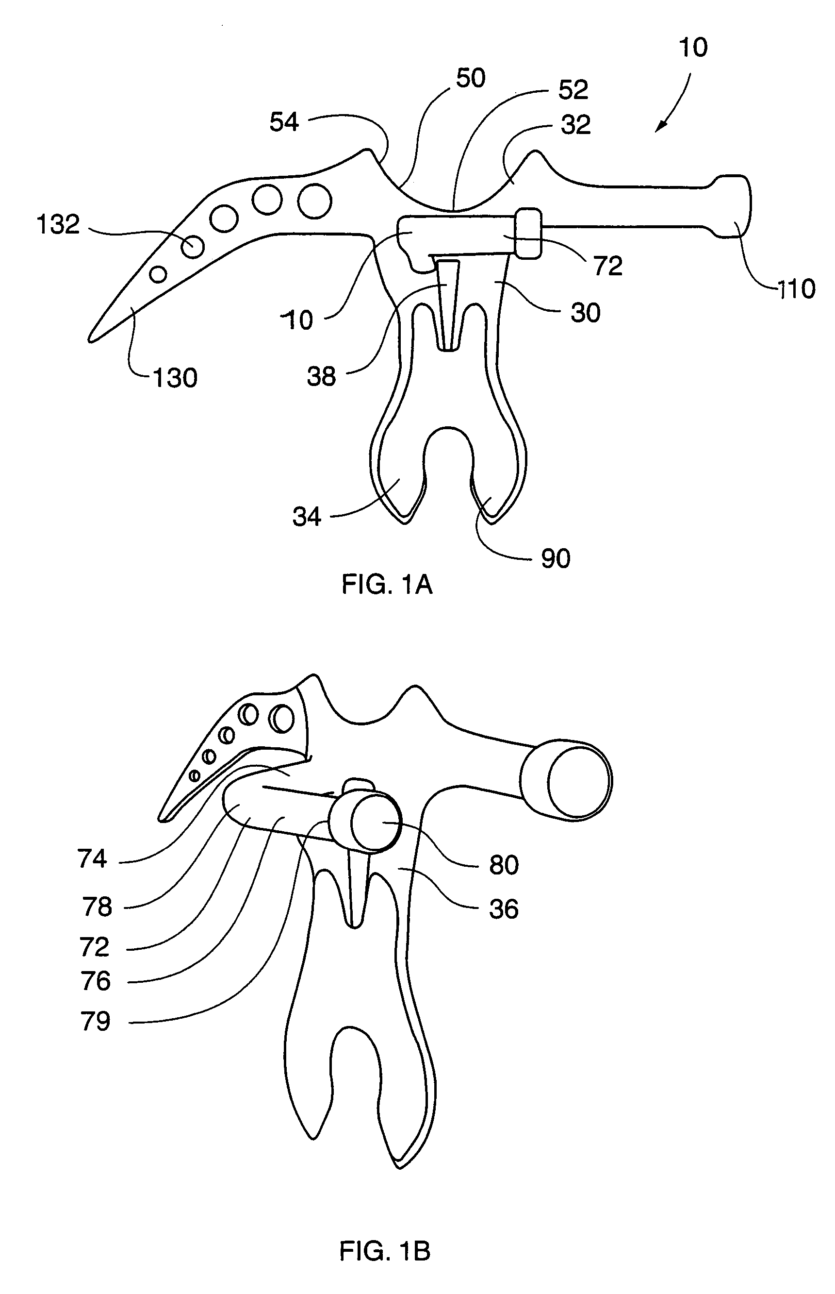
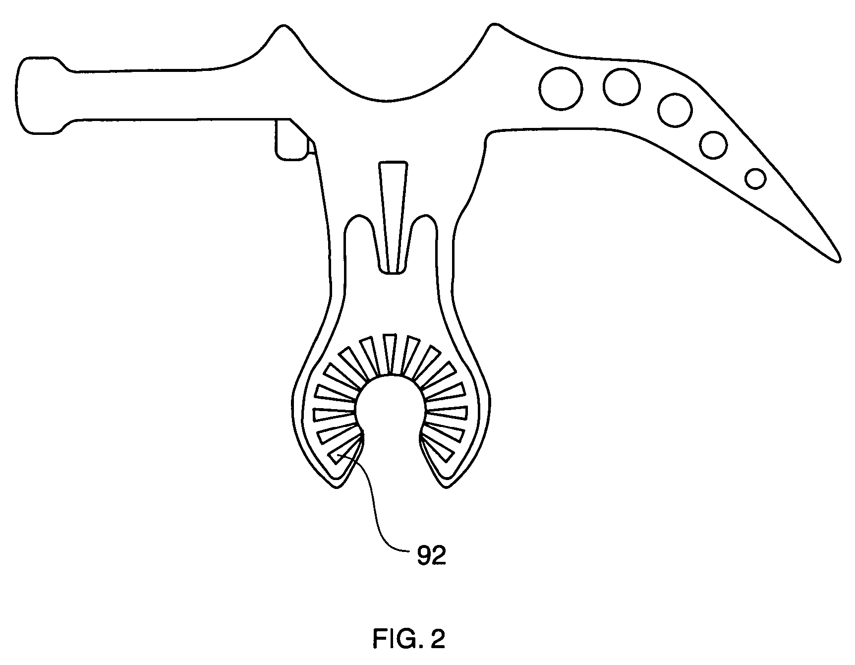
[0031]Referring now to FIGS. 1A–B and 2, the present invention in the preferred embodiment is line work tool device 10, and method thereof, comprising central body member 30, tool guidance structure 50, ring engagement member 70, mount structure 90, prong member 110, and claw member 130. It is important to understand that the present invention is suitable for utilization for any manipulative technique requiring use of such a tool in combination with a generally elongated support member, generally arms-length or greater, such as, for exemplary ...


PUM


Abstract

A line work tool device and method, wherein a tool guidance structure is provided for tool positioning assistance relative to the target workpiece, such as a high voltage switch, and wherein a unique inverted “L” shaped member extends from the device in such a manner as to facilitate interaction with the switch barrel.

Description

FIELD OF THE INVENTION[0001]The present invention relates generally to line work tools, and more particularly, to a line work tool device and method thereof, wherein uniquely shaped tool components facilitate manipulation of high voltage connections and the like. The present invention is particularly suited for, although not limited to, use as a disconnect tool, wherein utilization of the line work tool device via a hot stick enables quick, consistent contact with a cut-out barrel, and easy and secure engagement of a switch barrel, or ring, thereby enabling reproducibly fast switch disconnection.BACKGROUND OF THE INVENTION[0002]Numerous line work tools are available for use on, or as a working component of, an elongated, insulated rod commonly referred to as a hot stick, or shotgun stick. Linemen typically stand on the ground, holding one end of the hot stick and directing the extended end bearing the line work tool in order to accomplish a given task. The line work tools are thus g...

Claims


Application Information

Patent Timeline
Patent Type & Authority Patents(United States)
IPC IPC(8): B25B23/16
CPCB25D1/00H02G1/04H01H31/006
Inventor RIDER, JACK H.
Owner RIDER JACK H
Learn More