Fuel filter with valve indicator

Inactive Publication Date: 2007-02-27
OLEARY PATRICK OWEN
View PDF5 Cites 21 Cited by
  • Summary
  • Abstract
  • Description
  • Claims
  • Application Information

AI Technical Summary

Benefits of technology

[0017]In various exemplary embodiments an urging member assists the valve head in moving from a first position to second position. The urging member urges the valve head, stem and flag indicator to a fully deployed position such that the flag indicator is clearly visible in the transparent portion of the valve assembly on the external portion of the filter housing. The urging member also assists the valve head to advance within the valve assembly to allow fuel flow into the secondary chamber. The urging member may assis

Problems solved by technology

It is often difficult to make an exact determination of when a fuel filter has reached the end of its useful life.
In the case of fuel filters that have transparent housings, a discoloration of the filter media may be taken for a clogged filter condition, causing the user to prematurely change a functioning fuel filter.
Even when particulate matter or contaminants are clearly visible on the filter media, it is still difficult to accurately determine the true fuel flow across the filter media.
Depending on the location of the fuel filter, for example in the engine compartment of a vehicle or other device, it may be difficult for t

Method used


Image

  • Fuel filter with valve indicator
  • Fuel filter with valve indicator
  • Fuel filter with valve indicator

Examples


Embodiment Construction

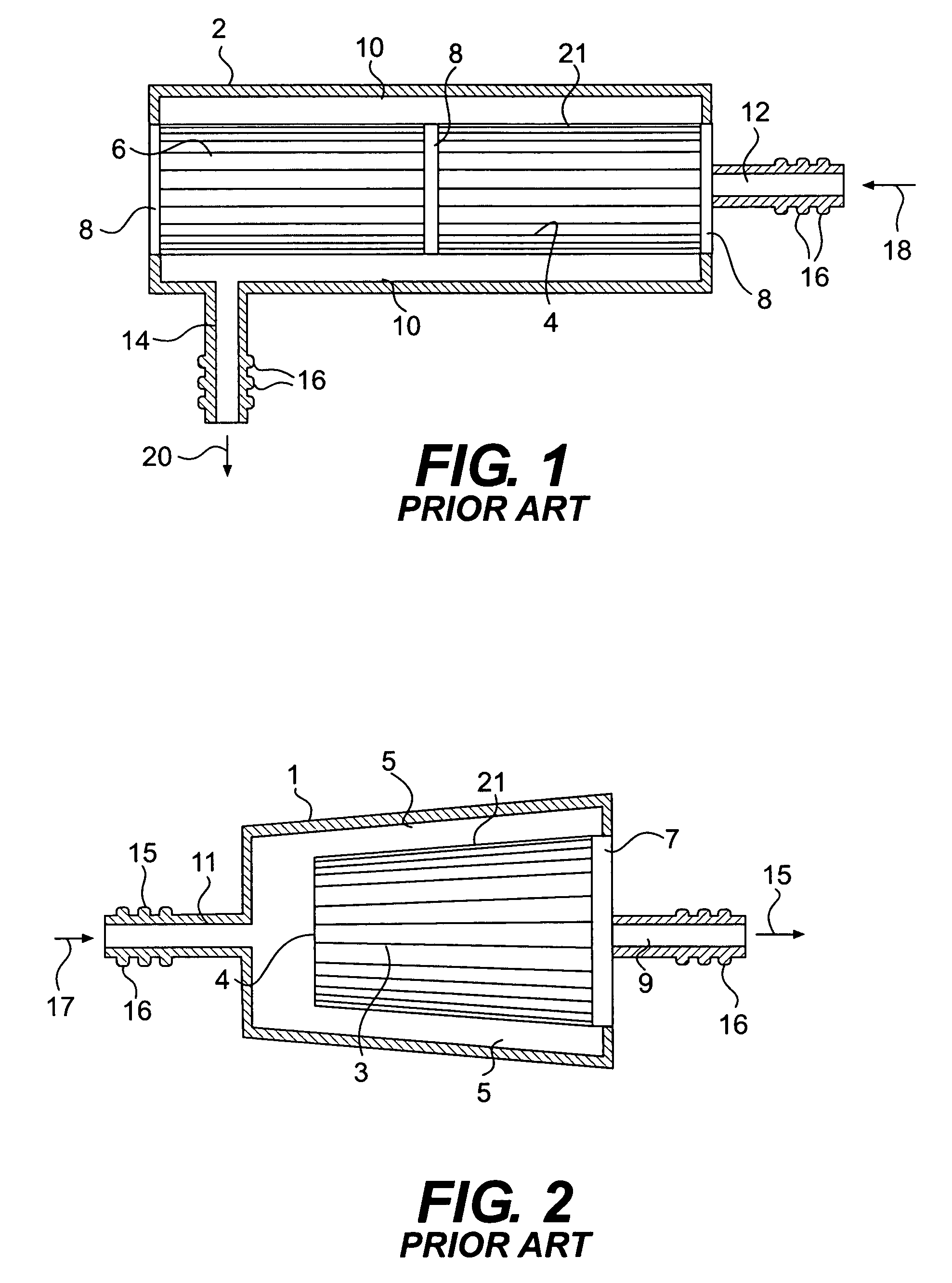
[0030]FIG. 1 illustrates a cross-sectional side view of a fuel filter of the prior art. This fuel filter has a housing 2 that encases a cylinder shaped filter element 4. The housing 2 has an inlet 12 and an outlet 14, each having ribs 16 that facilitate connection to fuel lines (not shown). Typically, the fuel lines would be clamped in place onto the inlet 12 and outlet 14. The filter element 4 may consist of a cylinder shaped filter media 21 that is held in place by filter media retainers 8. The filter media retainers 8 may vary in size, shape and location and may act to reinforce the filter media 21. The housing may be removed and the filter element 4 may be cleaned or replaced. Unfiltered fuel from the fuel tank flows into the filter via inlet 12 in flow direction 18. The unfiltered fuel then passes into the internal chamber 6, through the filter media 21, through the external passage way 10 to the outlet 14 and on to the carburetor or fuel injectors (not shown) in flow direction...


PUM

PropertyMeasurementUnit
Flow rateaaaaaaaaaa
Flexibilityaaaaaaaaaa
Transparencyaaaaaaaaaa

Abstract

A fuel filter includes a first filter chamber, a second filter chamber and a valve assembly disposed between the first and second filter chambers. The valve assembly includes a valve casing with a valve head connected to a flag indicator slidably disposed within the valve casing and movable between a first and second position. A port located in the valve casing allows fuel to flow from the first filter chamber to the second filter chamber when the valve head and flag indicator moves from the first position to the second position. A transparent portion of the valve casing allows the flag indicator to be visible in the second position allowing a user to determine that the fuel filter must be serviced or removed and replaced.

Description

BACKGROUND OF THE INVENTION[0001]1. Field of Invention[0002]This invention relates to fuel filter assemblies. Specifically, this invention relates to a fuel filter having a valve and flag indicator that signals a user when the fuel filter should be replaced.[0003]2. Description of Related Art[0004]Various types of fuel filters are known in the prior art. In the case of internal combustion engines, fuel filters insure that clean, filtered fuel is delivered by a fuel pump from a fuel tank to an engine's carburetor or fuel injectors. A typical fuel filter of the prior art may include a filter element enclosed in a housing having an inlet and outlet. The inlet and outlet allow the filter to be connected to a fuel system of an internal combustion engine. The filter element of a typical fuel filter may consist of a frame or reinforcing member connected to a filter media. The filter media may be constructed of a porous material, such as paper or other synthetic material. The filter media t...

Claims


Application Information

Patent Timeline
IPC IPC(8): B01D35/143B01D35/147
CPCB01D29/232B01D35/143B01D29/54B01D35/147
Inventor O'LEARY, PATRICK OWEN
Owner OLEARY PATRICK OWEN
Why Eureka
Try Eureka