
Apparatus and method for heating works uniformly through high frequency induction coils

a technology of induction coils and apparatus, which is applied in lighting and heating apparatus, drying machines with progressive movements, furnaces, etc., can solve the problems of difficult temperature control and precise control, and achieve the effects of limited work size, enhanced output, and limited work size of uniformly heat-able work

Active Publication Date: 2007-02-27
YOSHINO KOSAKUJO
View PDF15 Cites 12 Cited by
  • Summary
  • Abstract
  • Description
  • Claims
  • Application Information

AI Technical Summary

Benefits of technology

Enables continuous, controlled heating of multiple works of different sizes and shapes, reducing temperature differences across the work surface and improving the uniformity of heating, thus enhancing the strength of coatings and eliminating the need for external heating or degreasing.

Problems solved by technology

This is because precise control of temperature is difficult in the high frequency induction-heating technology.
However, in the high frequency induction-heating technology, works generate heat in itself.

Method used


Image

  • Apparatus and method for heating works uniformly through high frequency induction coils
  • Apparatus and method for heating works uniformly through high frequency induction coils
  • Apparatus and method for heating works uniformly through high frequency induction coils

Examples


first embodiment

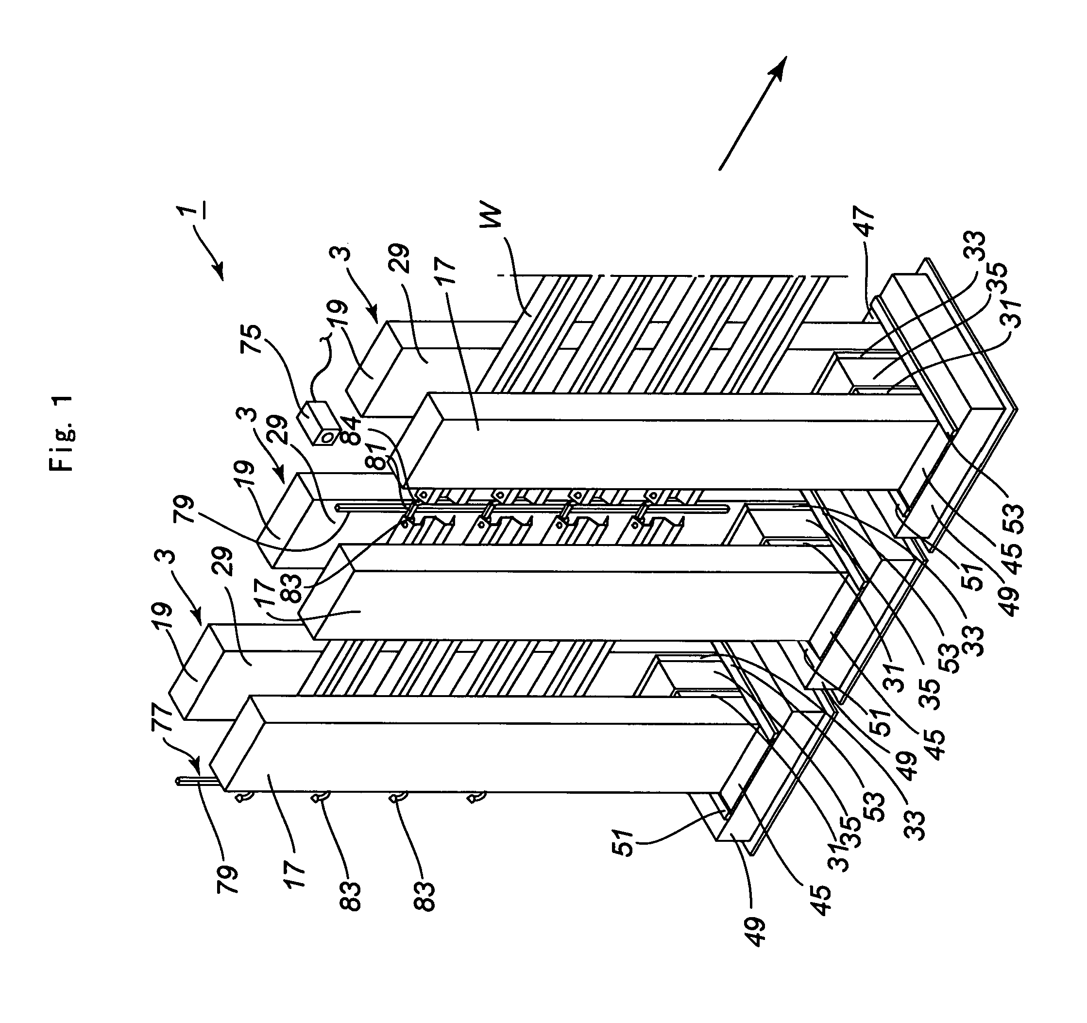
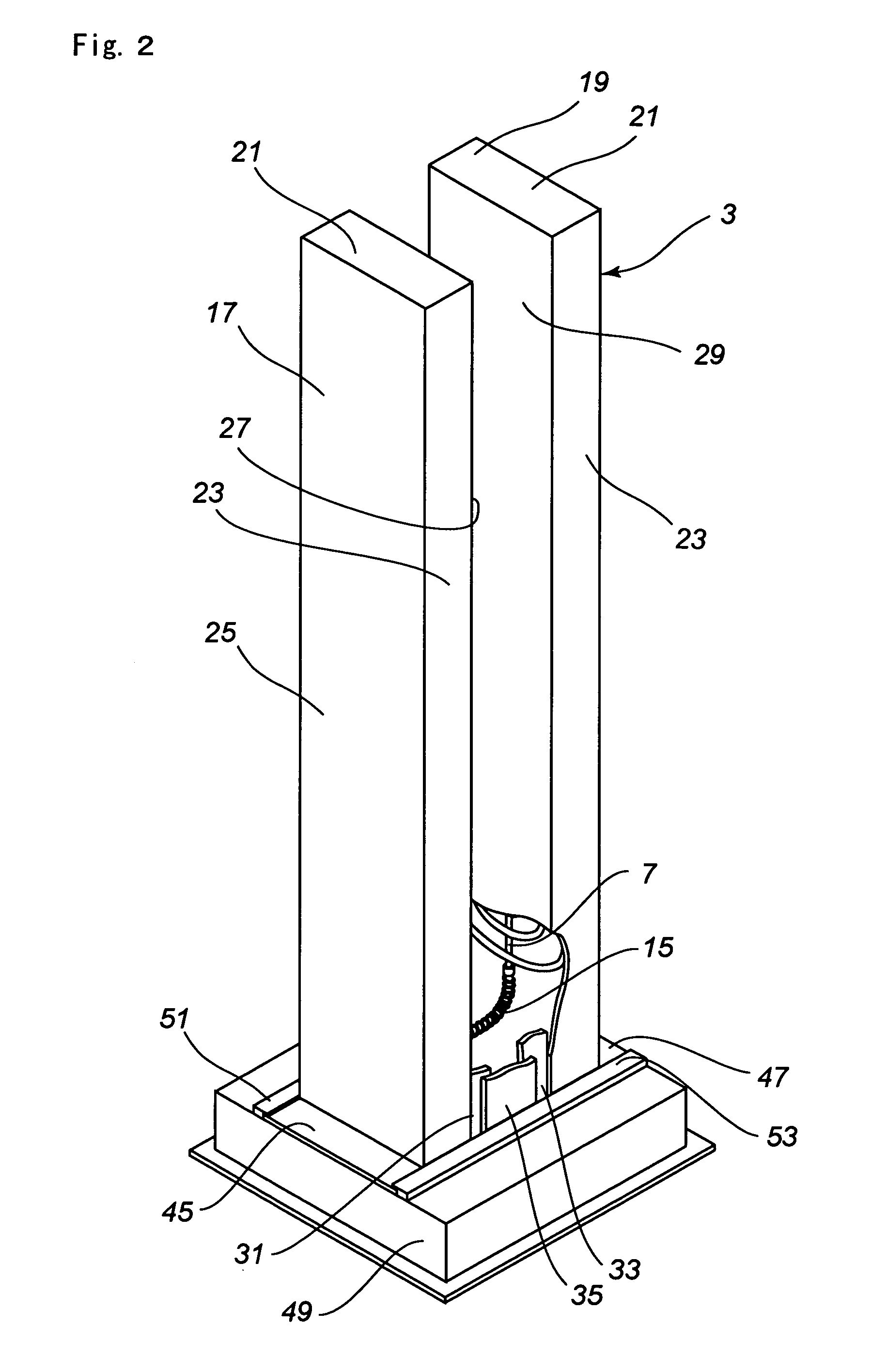
[0025]An apparatus 1 for heating a work (W) in accordance with the invention will now be described with reference to FIGS. 1–12.

[0026]The reference numeral 3 designates a high frequency induction-heating device 3 including a pair of opposite work coils 5, 7 positioned opposite.

[0027]The work coils 5, 7 are formed of a copper tube 9 wound to form a pair of swirl shaped coils as shown in FIGS. 2 and 3. The pitch (P) of each swirl is reduced gradually toward the central portion to eliminate cancellation out of the eddy currents.

[0028]The coils 5, 7 are connected with each other through an electrically conductive flexible cooling conduit 15. Remaining end portions of the coils 5,7 are also connected with a pair of conduits 15.

[0029]Thus obtained structure in which the coils 5, 7 are connected through one flexible conduit 15 is suitable for use in limited space.

[0030]The electrically conductive flexible cooling conduit 15 includes a flexible water tube 16 and flexible copper wires 18 bra...

second embodiment

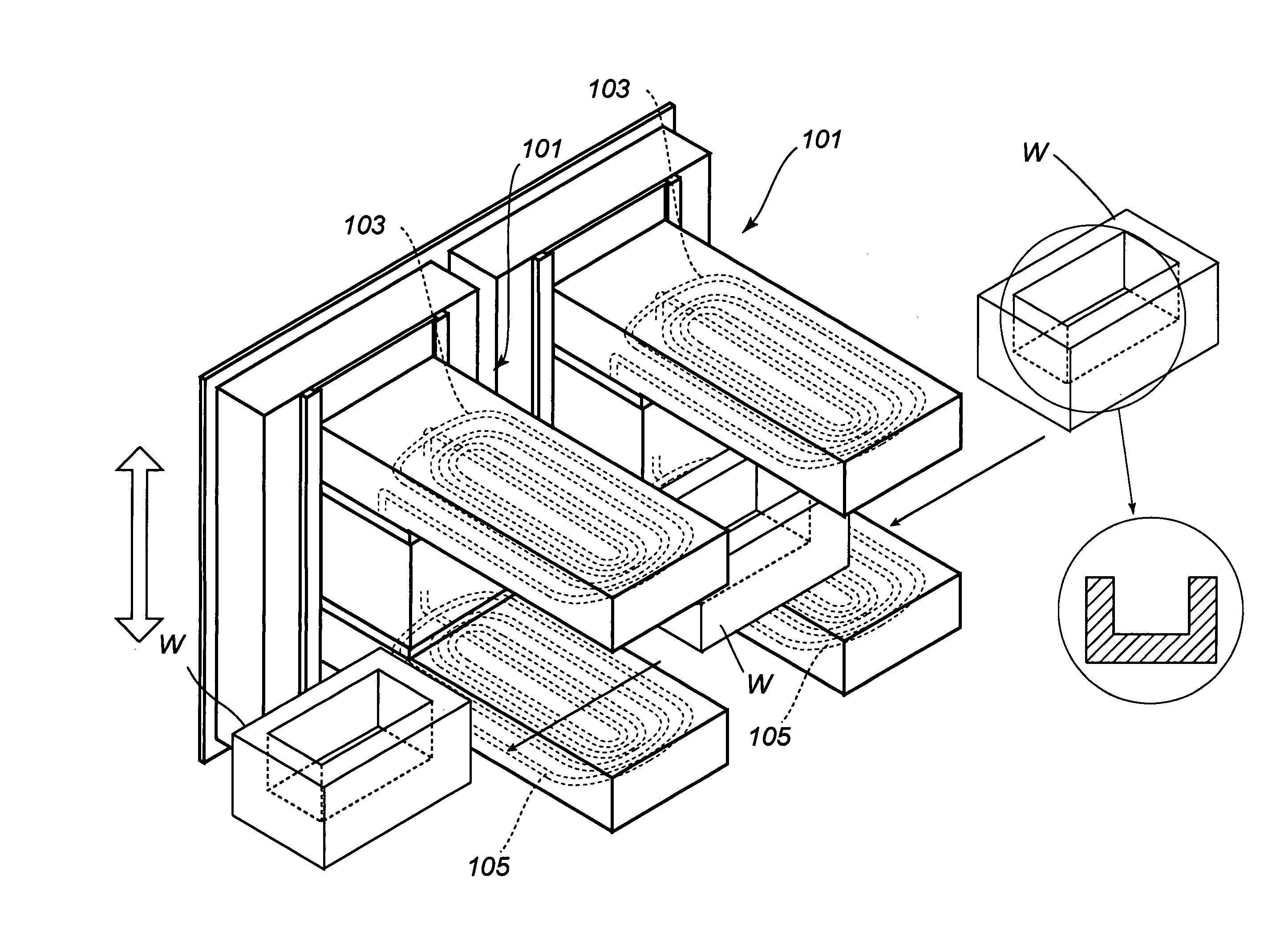
[0088]the present invention will now be described with reference to FIG. 12.

[0089]The unique feature of the high frequency induction-heating device designated generally by the reference numeral 101 is that a pair of work coils 103, 105 is disposed opposite to each other in the vertical direction. In other words, each coil extends horizontally. The work (W) to be heated is an upwardly opened box shaped blank having a cross section as illustrated within the circle. It is necessary to control the temperature of the work (W) accurately for heating the work (W) of such configuration uniformly. In this connection, it is desirable to place the work coils 103 and 105 vertically and to adjust the vertical distance from the work.

[0090]While particular embodiments of the present invention have been illustrated and described, it should be obvious to those skilled in the art that various changes and modifications can be made without departing from the spirit and scope of the invention.

[0091]For ...


PUM

PropertyMeasurementUnit
thicknessaaaaaaaaaa
lateral distanceaaaaaaaaaa
widthaaaaaaaaaa

Abstract

A high frequency induction-heating device 3 of the apparatus 1 for heating work includes a pair of opposite work coils accommodated within the coil casings 17 and 19 respectively. The casings 17 and 19 can be displaced in a unit by a motor provided under the device. Thus, the distance between the pair of work coils, and the distance between the work (W) and each work coil can be adjusted. The apparatus includes a plurality of heating devices 3 to which high frequency power sources are provided respectively. The apparatus and method for heating of a work with the apparatus is capable of treating a plurality of works (W) continuously under controlled conditions on work coil shapes and positions depending on the size and / or the shape of the works (W).

Description

BACKGROUND OF THE INVENTION[0001]The present invention relates to an apparatus and a method for heating relatively larger and / or complex shaped works uniformly without occurring over baking or short of baking.DESCRIPTION OF THE PRIOR ART[0002]High frequency induction-heating technology have been used only to heat small work one by one or to heat the work of uniform profile such as a pipe. This is because precise control of temperature is difficult in the high frequency induction-heating technology.[0003]However, in the high frequency induction-heating technology, works generate heat in itself. Thus, when the induction-heating technology is used to bake powder-coated works, the coating is heated from the surface of the work so that the coating can be secured more strongly. Degreasing operation can be omitted because oils and the like are evaporated and removed. Further, a dome-shaped drying facility is not required because the works are not heated from the outside.[0004]The applicant...

Claims


Application Information

Patent Timeline
Patent Type & Authority Patents(United States)
IPC IPC(8): H05B6/10H05B6/40B05D1/06H05B6/44B05D3/02C21D1/42F26B3/347F26B15/14F27D11/06F27D21/00H05B6/06H05B6/14
CPCB05D3/0281H05B6/14F26B3/347F26B15/14B05D1/06B05D2401/32B05C9/14
Inventor YOSHINO, KOSHIROYOSHINO, MASAHIROYOSHINO, YASUHIRO
Owner YOSHINO KOSAKUJO
Learn More